Vehicle lock controlled by a shape memory alloy actuator
a technology of shape memory and actuator, which is applied in the direction of carpet fasteners, dwelling equipment, applications, etc., can solve the problems of expensive redesign of pre-existing latches and lack of packaging space in the door, and achieve the effect of reducing packaging requirements and keeping costs low
- Summary
- Abstract
- Description
- Claims
- Application Information
AI Technical Summary
Benefits of technology
Problems solved by technology
Method used
Image
Examples
second embodiment
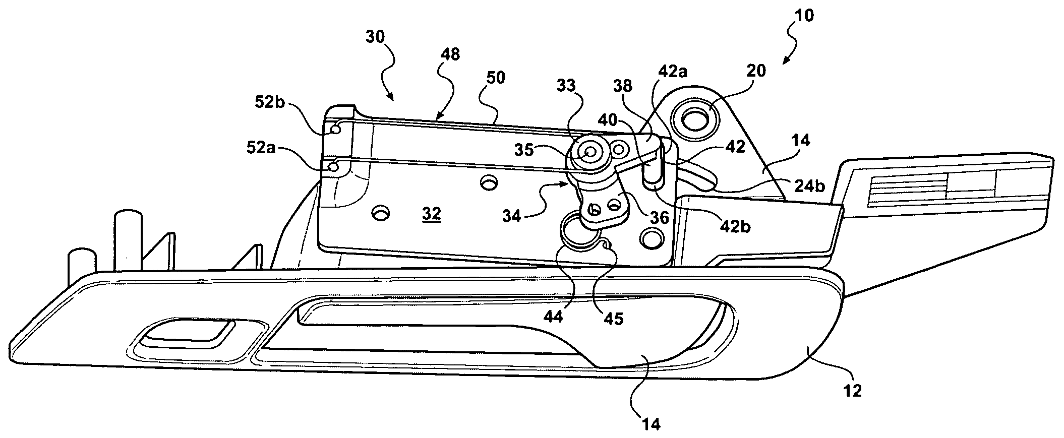
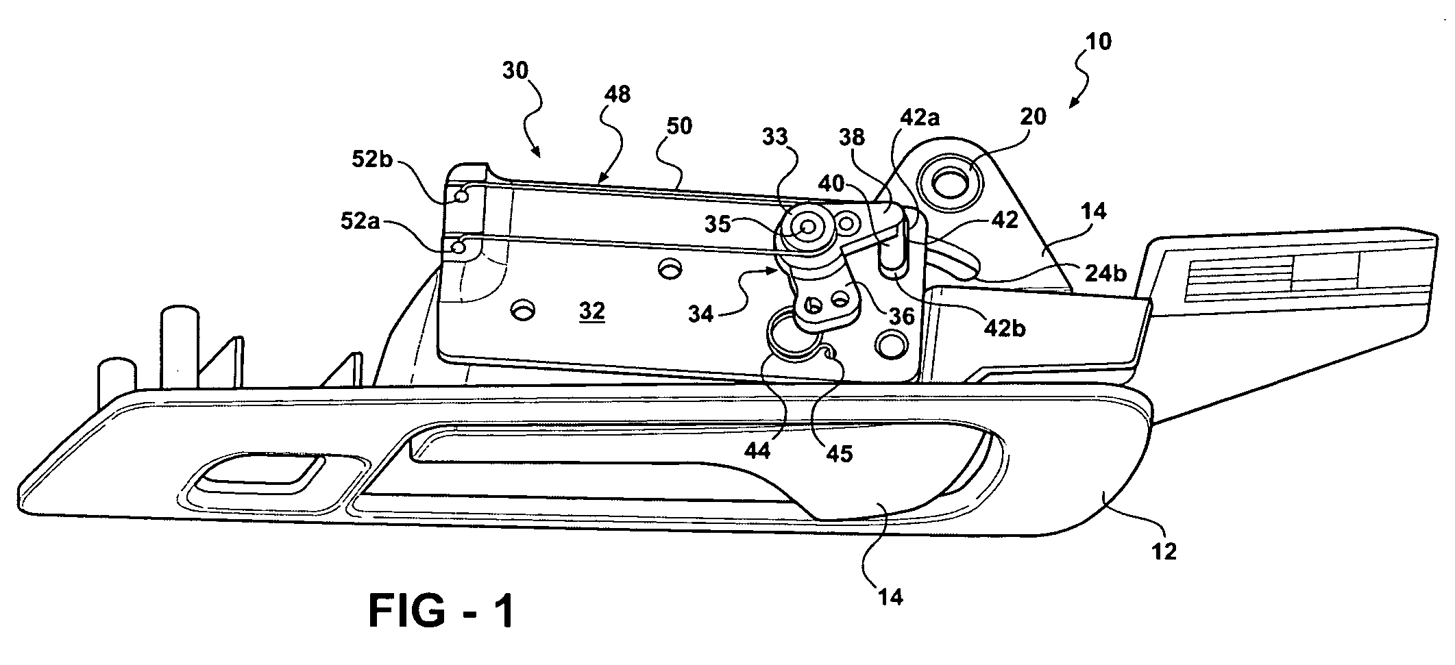
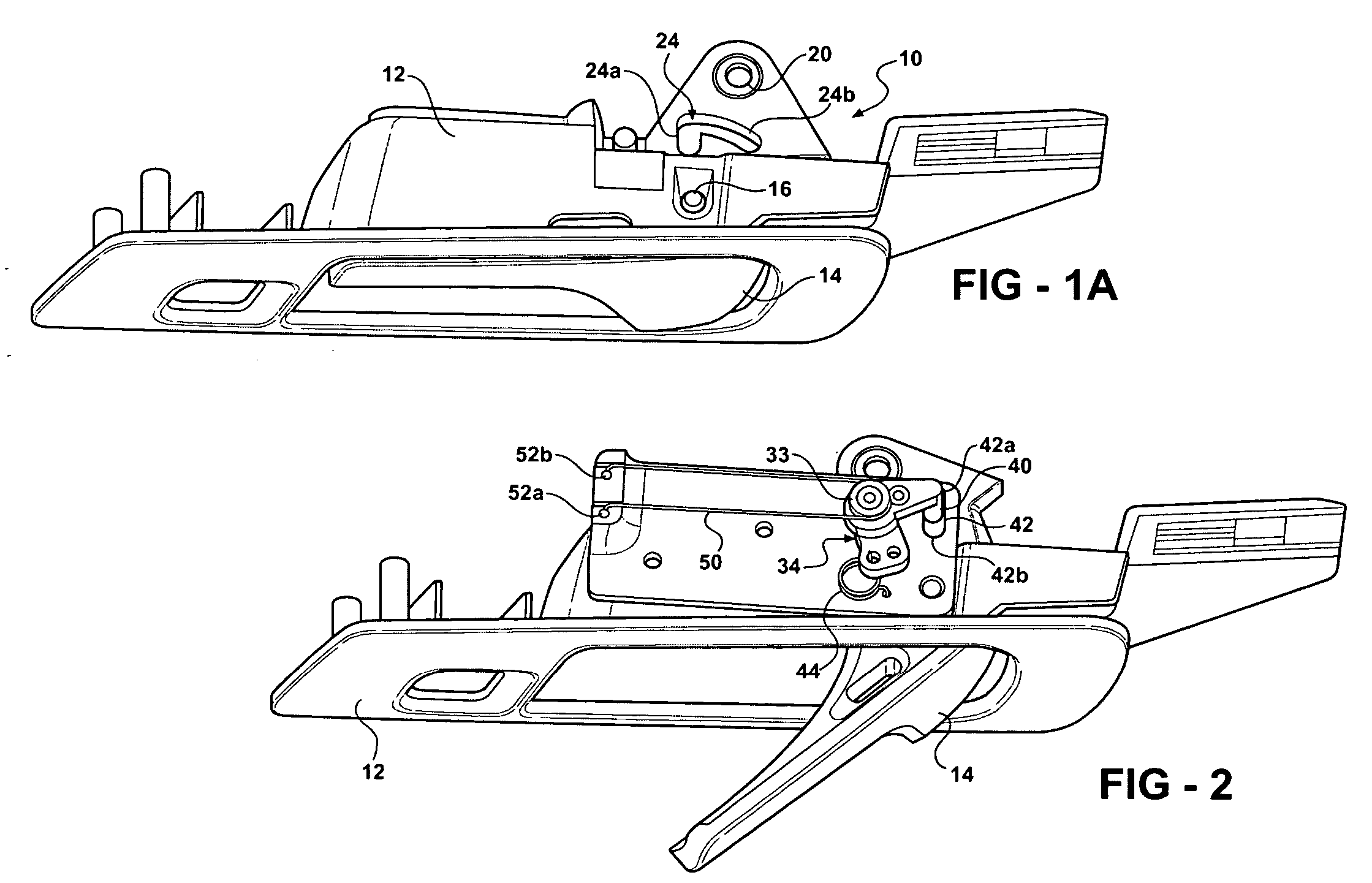
[0034] In the embodiment described above, the door handle lever 14 is prevented from moving when the child lock is engaged. In a second embodiment described below with reference to FIGS. 6-10, the door handle lever is always movable. This is made possible by directly coupling of the latch to an intermediate latch release lever and selectively coupling the door handle lever to the intermediate release lever via a link lever and the floating pin. When the child lock is engaged, the door handle lever is kinematically coupled to the latch release lever (and thus enabled) and when the child lock is disengaged the door handle lever is kinematically uncoupled from the latch release lever (and thus disabled).
[0035] More particularly, FIGS. 6-10 show a door handle and child lock assembly 58 in which door handle lever 14 is connected to a latch release lever 60 and a link / toggle lever 70 via a floating pin 80. The latch release lever 60 is pivotally mounted to a post 116 of housing 112, which...
first embodiment
[0040] In a manner similar to the first embodiment described above, the sleeve 76 is set to a predetermined voltage and the end terminal of each wire section 151, 152 is selectively switched between this voltage or ground. The switches are controlled by a controller (not shown) which establishes the current flow in wire sections 151 and 152 in order to selectively actuate the link / toggle lever 60 to the first or second positions in accordance with a command signal.
third embodiment
[0041] Referring now to FIGS. 11, 12a and 12b, the invention is shown. In this embodiment, the shaped memory actuator is mounted to the latch housing and directly pivots a child lock lever between a locked and an unlocked position. Latch 160 includes a child lock lever 162 pivotally mounted to latch housing 164 via a child lock pin 166. Child lock lever 162 is movable between a locked and an unlocked position. As can more clearly be seen in FIG. 12a, a claw 168 on child lock lever 162 retains an end of a lock link lever (not shown). By pivoting child lock lever 162 between the locked and unlocked positions, the lock link lever kinematically couples or decouples the inner door handle from the release lever (also not shown). The inner door handle can also be decoupled in order to provide a double-locking feature, if desired. A toggle spring (not shown) may be used to bias the child lock lever 162 to the locked or unlocked positions, if desired.
[0042] Retained within latch housing 164 ...
PUM
 Abstract
Description
Claims
Application Information
 - R&D
- Intellectual Property
- Life Sciences
- Materials
- Tech Scout
- Unparalleled Data Quality
- Higher Quality Content
- 60% Fewer Hallucinations
Browse by: Latest US Patents, China's latest patents, Technical Efficacy Thesaurus, Application Domain, Technology Topic, Popular Technical Reports.
© 2025 PatSnap. All rights reserved.Legal|Privacy policy|Modern Slavery Act Transparency Statement|Sitemap|About US| Contact US: help@patsnap.com


