Optical components and passive optical network pon systems

A technology of optical components and optical devices, which is applied in the field of communication, can solve problems such as increasing equipment costs, increasing costs, and limited power consumption, and achieves the effects of reducing costs, reducing power consumption, and reducing packaging requirements

Active Publication Date: 2016-11-30
HUAWEI TECH CO LTD
View PDF5 Cites 0 Cited by
  • Summary
  • Abstract
  • Description
  • Claims
  • Application Information

AI Technical Summary

Problems solved by technology

As the transmission rate of the optical module increases, the number of channels it contains is also increasing, which makes the power consumption of the optical module more and more large. Usually, the optical module adopts a Small Form Pluggable (Small Form Pluggable, SFP) package or 10 The 10Gigabit Small Form Factor Pluggable (XFP) package supports limited power consumption and cannot meet the requirements of optical modules
[0003] In the prior art, the optical module is packaged by using a packaging mode that supports higher power consumption, which will greatly increase the cost; or reduce the number of optical modules on the communication board, which will lead to waste of performance of the communication board and also increase the equipment cost

Method used


Image

  • Optical components and passive optical network pon systems
  • Optical components and passive optical network pon systems
  • Optical components and passive optical network pon systems

Examples


Embodiment Construction

[0032] The following will clearly and completely describe the technical solutions in the embodiments of the present invention with reference to the accompanying drawings in the embodiments of the present invention. Obviously, the described embodiments are only some, not all, embodiments of the present invention. Based on the embodiments of the present invention, all other embodiments obtained by persons of ordinary skill in the art without creative efforts fall within the protection scope of the present invention.

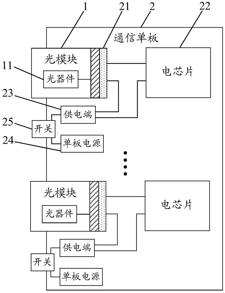
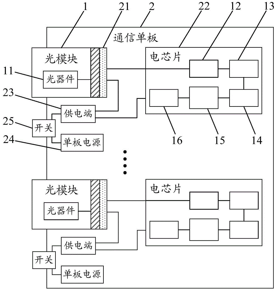
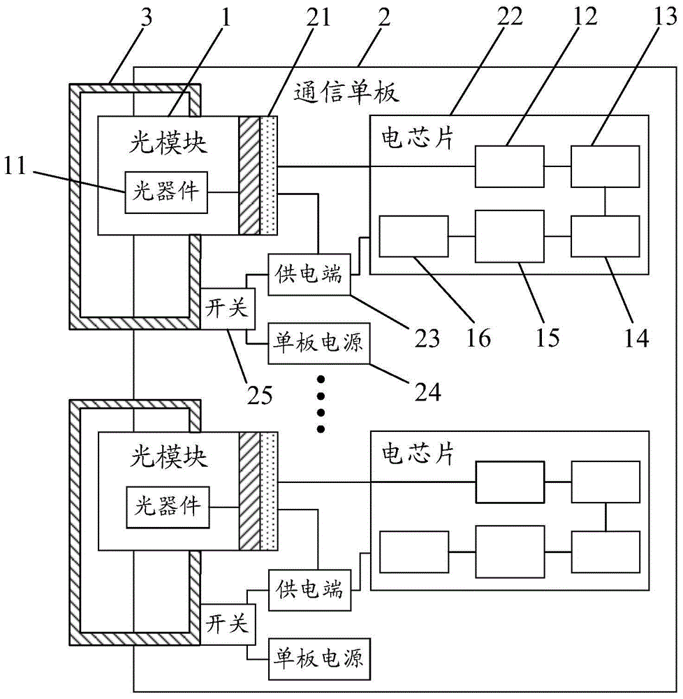
[0033] Such as figure 1 As shown, the embodiment of the present invention provides an optical component, including: an optical module 1 and a communication board 2; the communication board 2 is provided with an optical module interface 21; the optical module 1 is provided with an optical device 11 and connected to the optical device 11, the gold finger is used to insert the optical module interface 21 on the communication board 2; the communication board 2 is provi...


PUM


Abstract

The invention discloses an optical component and a passive optical network PON system, relates to the technical field of communication, and reduces the packaging requirements of the optical module, thus reducing the cost. The optical component includes: an optical module and a communication single board; an optical module interface is arranged on the communication single board; an optical device and a golden finger connected to the optical device are arranged on the optical module, and the golden finger It is used to insert the optical module interface on the communication single board; the electrical chip corresponding to the optical module is arranged on the communication single board; the communication pin of the electrical chip is connected to the communication pin of the optical module interface. Pins; a power supply terminal connected to the power supply pin of the optical module interface and the power supply pin of the electronic chip; a single board power supply connected to the power supply terminal through a switch.

Description

technical field [0001] The invention relates to the technical field of communication, in particular to an optical component and a PON system of a passive optical network. Background technique [0002] In the current optical communication system, the optical module is plugged on the communication single board through golden fingers. The optical module includes an optical device and an electrical chip. The optical device can be a bidirectional optical sub It can be a transmitting optical module (Transmitter Optical Sub Assembly, TOSA) plus a receiving optical module (Receiver Optical Sub Assembly, ROSA). As the transmission rate of the optical module increases, the number of channels it contains is also increasing, which makes the power consumption of the optical module more and more large. Usually, the optical module adopts a Small Form Pluggable (Small Form Pluggable, SFP) package or 10 The 10 Gigabit Small Form Factor Pluggable (XFP) package supports limited power consumpt...

Claims


Application Information

Patent Timeline
Patent Type & Authority Patents(China)
IPC IPC(8): H04B10/40H04Q11/00
Inventor 徐之光林华枫
Owner HUAWEI TECH CO LTD
Why Eureka
Try Eureka