Combination power circuit light coding system

a technology of power circuit and light coding system, which is applied in the direction of coupling device connection, emergency protective arrangement for limiting excess voltage/current, instruments, etc., can solve the problems of affecting the service life of the electrically-powered device, the lack of isolation of one or more electrical power problems, and the inability to provide information to the customer

Inactive Publication Date: 2005-07-07
COMP DATA EXCHANGE SERVICES
View PDF6 Cites 2 Cited by
  • Summary
  • Abstract
  • Description
  • Claims
  • Application Information

AI Technical Summary

Problems solved by technology

One problem with conventional power packs is the lack of isolation of one or more electrical power problems that can arise in a component part of the power pack.
For example, if an electrically-powered device such as a computer peripheral being powered by the power pack suddenly loses power, it is not immediately apparent whether the problem is with the electrical source into which an input power supply cable is plugged, the electrical source itself, the power pack, an associated circuit breaker or ground fault interrupt circuit within the power pack, a device power supply cable, or the electrically-powered device being powered.
Typically, when an electrical problem arises, the troubleshooting for an electrically-powered device and its power supply can be a difficult and expensive task.
Vendor service personnel contacted via telephone can be hindered by the lack of information supplied by the customer.
In some instances, the customer's description of an electrical problem incorrectly attributes the problem to either the printer or the power pack.
However, shipping costs as well as replacement part costs can be very expensive.
In these cases, the problem has been initially misdiagnosed by the vendor service personnel because of the customer's lack of information.
However, the burden of additional shipping and replacement part costs has already been incurred.

Method used


Image

  • Combination power circuit light coding system
  • Combination power circuit light coding system
  • Combination power circuit light coding system

Examples


Embodiment Construction

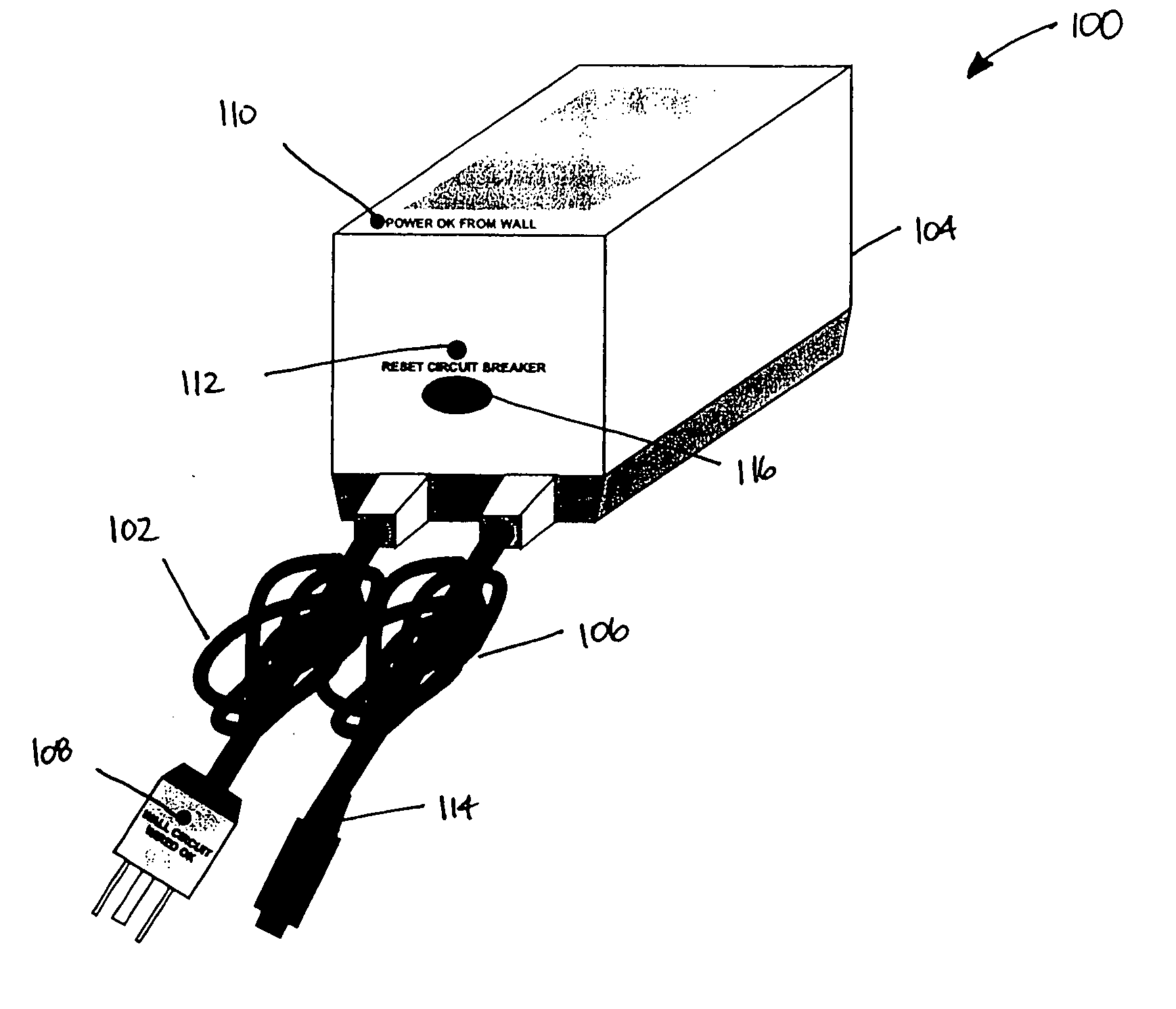
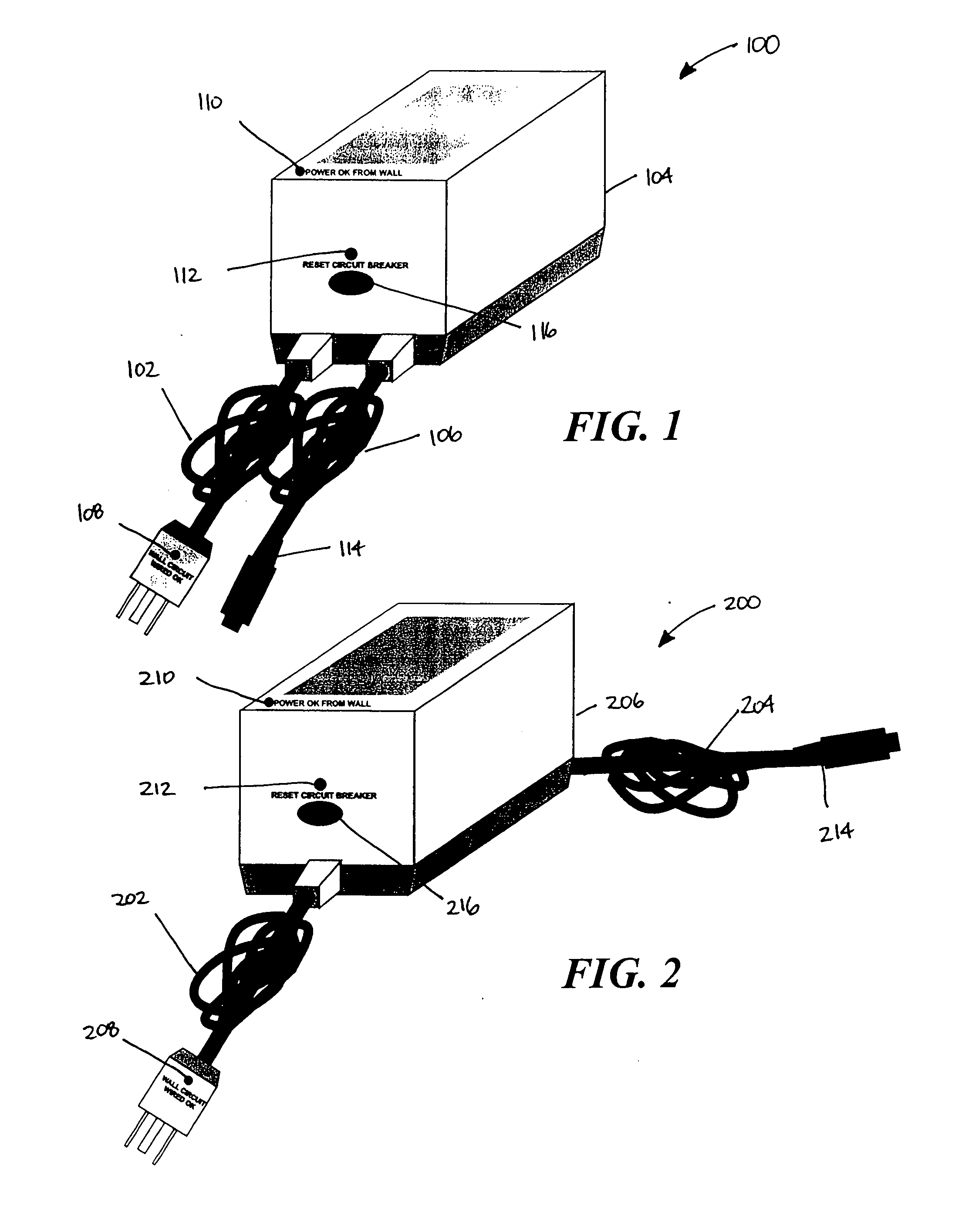
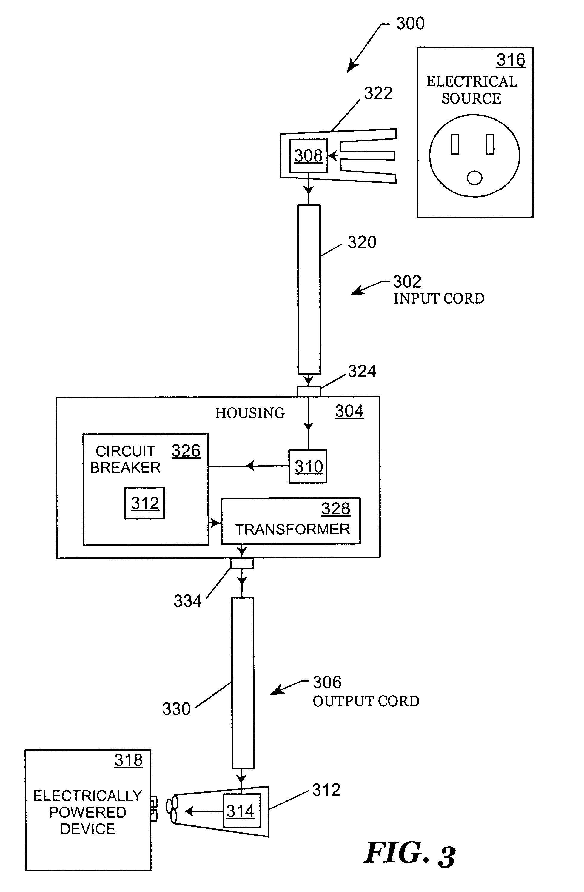
[0023]FIG. 1 is a system in accordance with various embodiments of the invention. The system 100 is a combination power circuit light coding system or device. Typically, the system 100 is utilized as a power transformer for an electrically-powered device such as a printer or other type of computer peripheral device. The system 100 is adapted to transfer electrical current from an electrical source, and is further adapted to transform an electrical current to usable electrical power for an electrically-powered device such as a printer or other type of computer peripheral device. In most cases, the electrical source is a conventional electrical outlet that provides a 120 VAC electrical current, such as standard household electrical outlet. The system 100 usually steps down the electrical current to a usable electrical power amount for an electrically-powered device. The system 100 includes an input cord 102, a housing 104, and an output cord 106. A combination or series of indicators ...


PUM


Abstract

Systems, methods, and apparatuses for isolating an electrical problem in a power pack include a system in accordance with various embodiments of the invention. The system includes a power pack. The power pack includes an input cord including at least a first indicator, wherein the input cord is adapted to receive electrical current from an electrical source, and further adapted to transmit the electrical current to the power pack, and wherein the first indicator indicates when the input cord transmits electrical current from the electrical source. The power pack also includes a housing including at least a second indicator, wherein the second indicator indicates when the power pack receives electrical current from the input cord. The power pack further includes a device cord adapted to conduct electrical current from the power pack to an electrically-powered device, the device cord including at least a third indicator, wherein the third indicator indicates when the power pack transmits electrical current through the device cord.

Description

CROSS-REFERENCE TO RELATED APPLICATIONS [0001] This application claims priority to U.S. provisional patent application Ser. No. 60 / 333,250, filed Nov. 14, 2001, which is incorporated herein by reference.FIELD OF THE INVENTION [0002] The invention relates in general to electronic diagnostic equipment, and relates more particularly to systems, methods, and apparatuses for identifying the location of an electrical problem in a power pack for an electrically-powered device. BACKGROUND OF THE INVENTION [0003] A conventional power transformer pack is also known as a “power pack” or “power supply.” An input cord or input power supply cord plugs into a conventional electrical AC outlet, and supplies electrical current to a power pack. The power pack transforms the electrical current to usable electrical current for an electrically-powered device. Some power packs may have a circuit breaker or a ground fault interrupt circuit built into the power pack. An output cord or device power supply c...

Claims


Application Information

Patent Timeline
Patent Type & Authority Applications(United States)
IPC IPC(8): H01R13/66H01R13/717
CPCH01R13/6675H01R13/7175H01R13/717
Inventor BARNA, JOSEPH A.
Owner COMP DATA EXCHANGE SERVICES
Why Eureka
Try Eureka