Low thermal mass, variable watt density formable heaters for printer applications

a printer and variable watt density technology, applied in the field of printing systems, can solve the problems of jamming of the internal printer mechanism, large number of shards and ink particles,

Inactive Publication Date: 2005-07-07
XEROX CORP
View PDF4 Cites 39 Cited by
  • Summary
  • Abstract
  • Description
  • Claims
  • Application Information

AI Technical Summary

Problems solved by technology

This last feature prevents the ink stick from breaking free from the heater plate, resulting in the creation of a large number of s

Method used


Image

  • Low thermal mass, variable watt density formable heaters for printer applications
  • Low thermal mass, variable watt density formable heaters for printer applications
  • Low thermal mass, variable watt density formable heaters for printer applications

Examples


Embodiment Construction

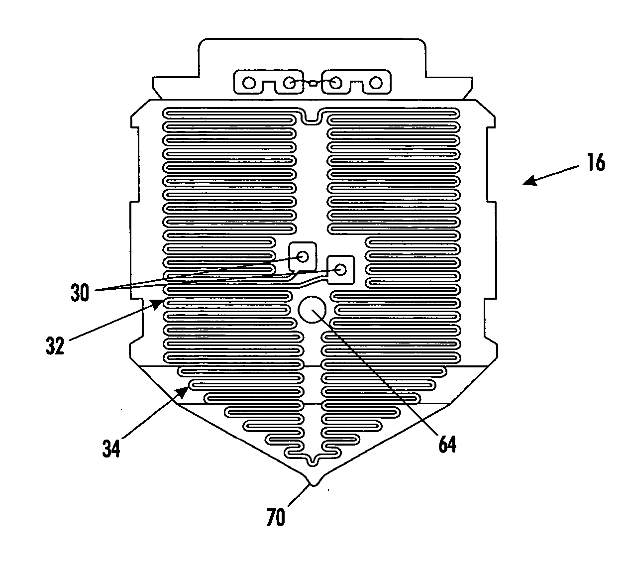
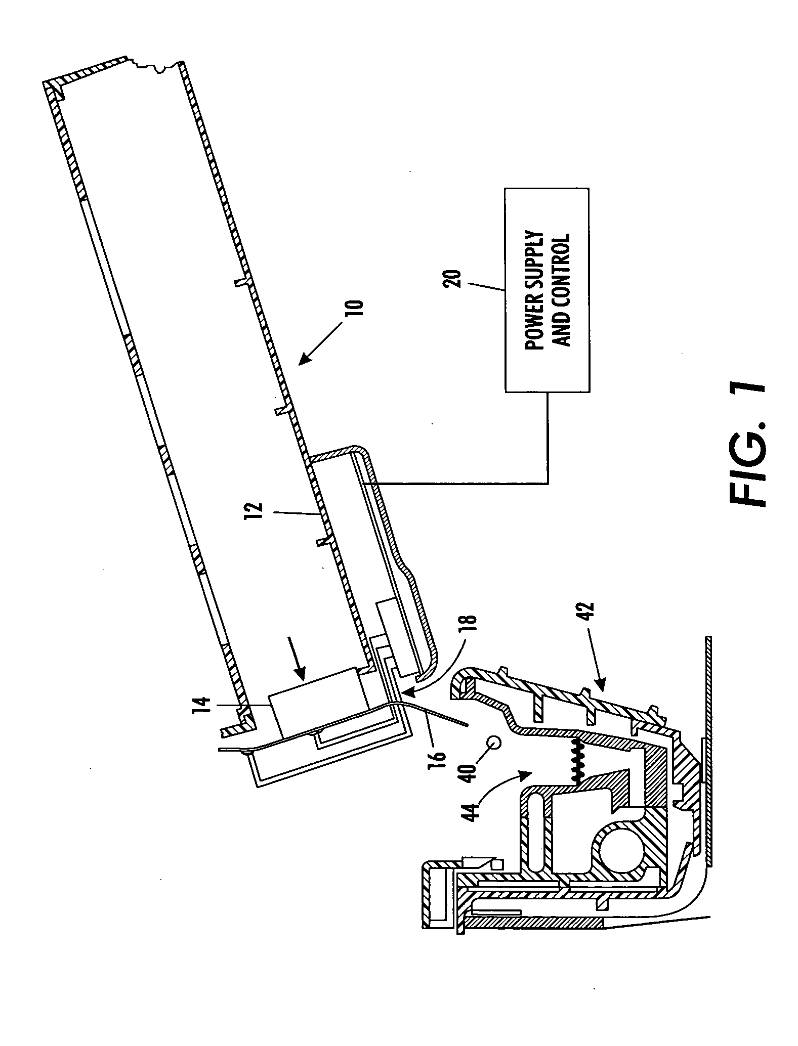
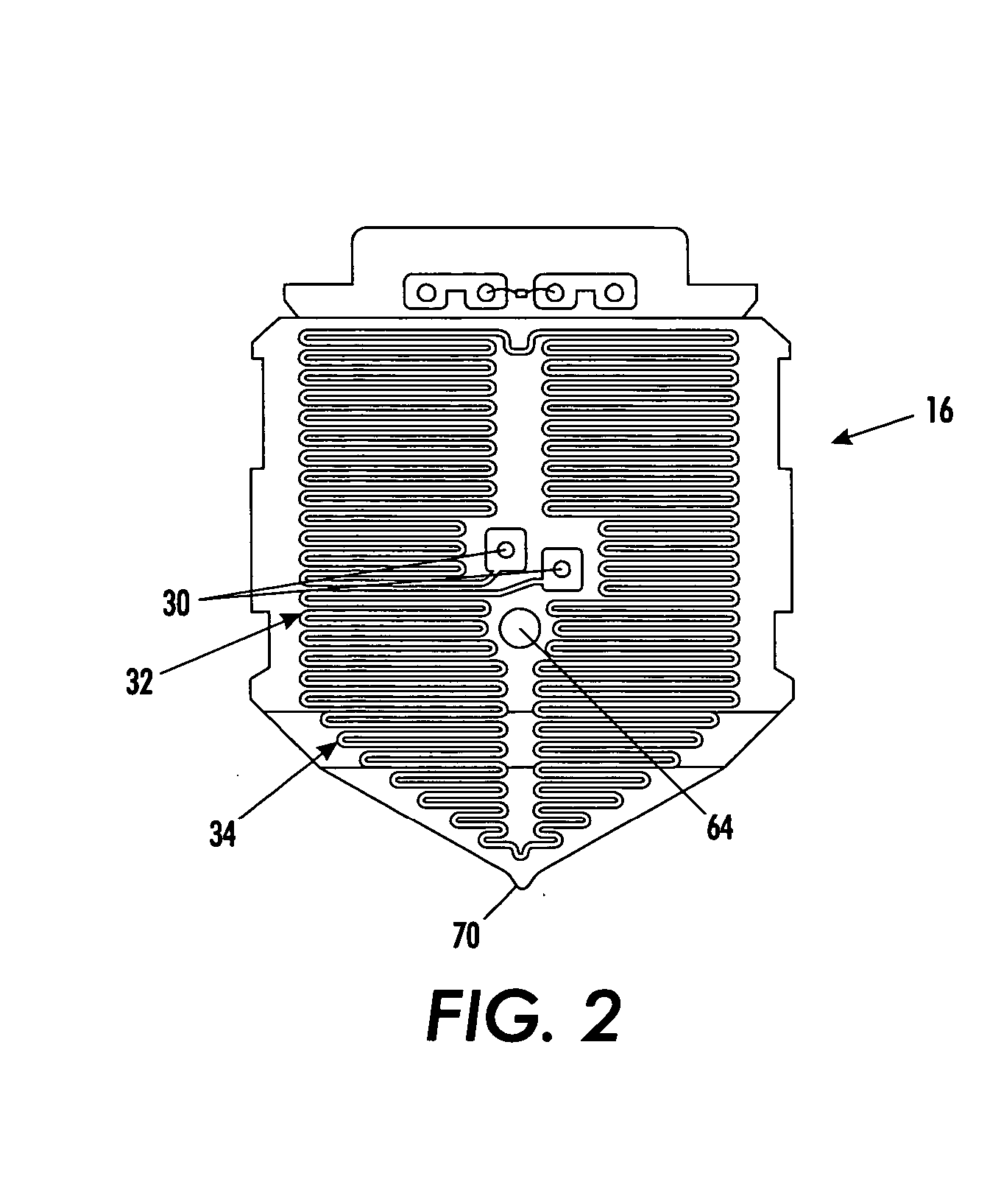
[0010] With reference to FIG. 1, the basic elements of an ink supply system in an ink “phase-changing” printing system can be seen. Ink loader assembly 10 includes a tray 12 for holding a solid phase ink stick 14. An ink melt heater 16 is disposed at an open end 18 of the tray to contact the ink stick and to allow for egress of liquid phase ink during heating from the tray 10. The heating plate 16 receives its heating energy from a power supply and control system 20. The heating element includes an assembly with resistance traces thereon so that electrical energy supplied thereto can be converted to heat energy.

[0011]FIG. 1 shows an ink drip 40 falling from the tray 10 at ink drip point 70 and the heating element 16 assembly into a print head assembly 42. Print head assembly 42 comprises a reservoir 44 to receive the melted ink and to communicate the ink to nozzles (not shown) within the print head assembly for printing on a document. It should be appreciated with reference to FIG....


PUM


Abstract

An ink melt heater is disposed in a phasing printing system for heating a solid ink stick for melting the ink stick from a solid to a liquid phase. The heater includes a trace assembly having a plurality of powerzones having different wattage densities respectively. The heat transfer plate is adhered to the trace assembly for mating engagement against the solid ink stick. The heater has a low thermal mass for enhanced and rapid heat transfer from the trace assembly through the transfer to the ink stick.

Description

BACKGROUND [0001] The present exemplary embodiments relate to printing systems and, in particular, printing devices which utilize a supply of color inks to be communicated to a print head for document printing. More particularly, the present embodiments utilize solid ink sticks as a supply ink, which must be heated to a liquid form before being capable of communication to the print head. Such systems are commercially available under the PHASOR® mark from Xerox Corporation. [0002] The present embodiments concern the structure of the heater element that melts the solid ink stick to a liquid form. [0003] The basic operation of such phasing printing systems comprises the melting of a solid ink stick, its communication to a reservoir for interim storage, and then a supply process from the reservoir to a print head for printing of a document. In the melting of the ink stick, a relatively large amount of thermal energy is needed to be applied in a very small area. Accordingly, the heating ...

Claims


Application Information

Patent Timeline
IPC IPC(8): B41J2/175
CPCB41J2/17593
Inventor GODIL, AMIN M.HINDMAN, LARRY E.
Owner XEROX CORP
Why Eureka
Try Eureka