Stent to be deployed on a bend

Inactive Publication Date: 2005-07-07
BOSTON SCI SCIMED INC
View PDF45 Cites 120 Cited by
  • Summary
  • Abstract
  • Description
  • Claims
  • Application Information

AI Technical Summary

Benefits of technology

[0011] In another embodiment, a stent may comprise a plurality of interconnected struts defining a wall surface. The wall surface may include a segment having a strip extending from one end of the segment to the other e

Problems solved by technology

This arrangement typically provides poor scaffolding on the outside of the

Method used


Image

  • Stent to be deployed on a bend
  • Stent to be deployed on a bend
  • Stent to be deployed on a bend

Examples


Example

[0027] This invention may be embodied in many different forms. This description is an exemplification of the principles of the invention and is not intended to limit the invention to the particular embodiments illustrated.

[0028] For the purposes of this disclosure, unless otherwise indicated, identical reference numerals used in different figures refer to the same component.

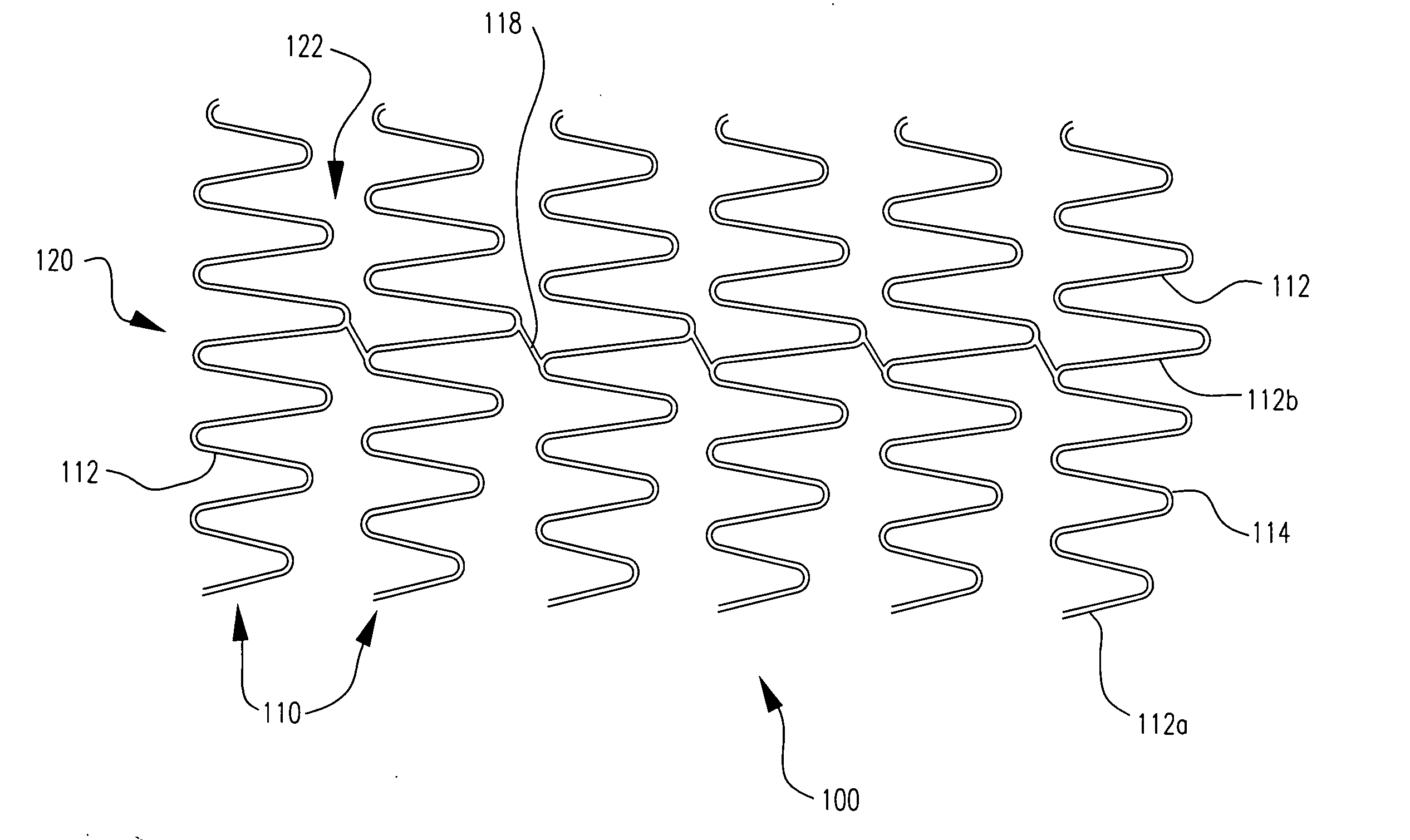
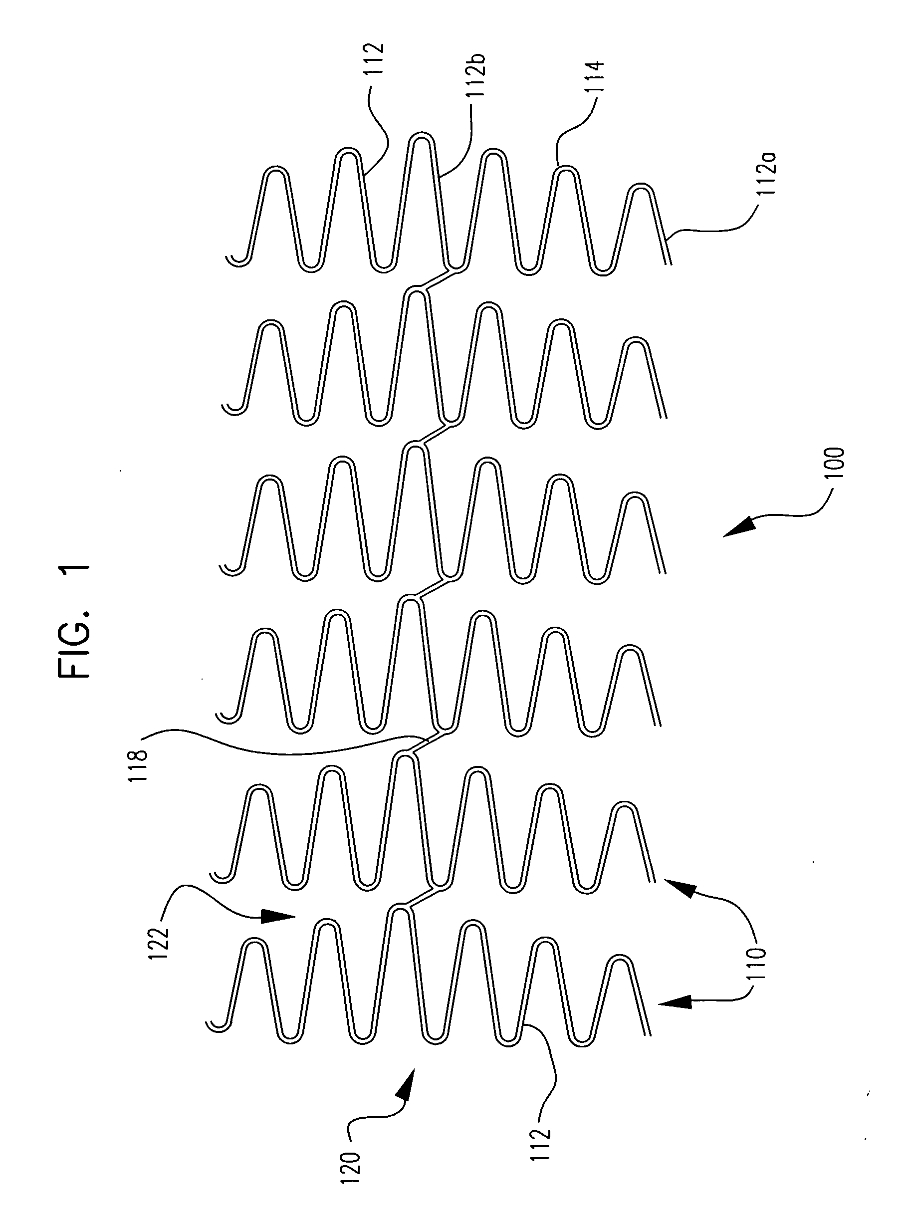
[0029] In one embodiment, the invention is directed to a stent, such as that shown at 100 in FIG. 1, comprising a plurality of interconnected closed serpentine circumferential bands 110. Adjacent closed serpentine circumferential bands 110 may be connected to one another by at least one connecting element 118. Each closed serpentine circumferential band 110 comprises a plurality of struts 112. Struts 112 which are circumferentially adjacent to one another are connected to one another by a turn 114. The length of the struts 112 within a band 110 generally increases in length from a minimum strut length to a maxi...


PUM


Abstract

A stent comprises a segment having a plurality of interconnected closed serpentine circumferential bands. Each closed serpentine circumferential band comprises a plurality of struts. Struts which are circumferentially adjacent one another are connected one to the other by a turn. Each strut has a length. The struts generally increase in length from a minimum strut length to a maximum strut length and then generally decrease in length from the maximum length to the minimum length as the circumferential band is traversed in its entirety in a clockwise direction. The maximum length struts of adjacent closed serpentine circumferential bands may be longitudinally aligned.

Description

BACKGROUND OF THE INVENTION [0001] Stents are placed or implanted within a variety of bodily vessels including in coronary arteries, renal arteries, peripheral arteries including illiac arteries, arteries of the neck and cerebral arteries, veins, biliary ducts, urethras, fallopian tubes, bronchial tubes, the trachea, the esophagus and the prostate. [0002] Stents are available in a wide range of designs. One popular stent design includes a plurality of serpentine rings having alternating turns. The rings are made of interconnected struts. Adjacent rings are interconnected via connecting elements. [0003] Generally, when stents are deployed in areas of high curvature they are bent so that the struts on the outside of the curve are farther apart than those on the inside of the curve. This arrangement typically provides poor scaffolding on the outside of the bend and / or possibly result in overlapping struts on the inside of the bend. [0004] There remains a need for stents which provide a...

Claims


Application Information

Patent Timeline
IPC IPC(8): A61F2/06A61F2/90
CPCA61F2/856A61F2/91A61F2/915A61F2002/91508A61F2230/0054A61F2002/91558A61F2250/0018A61F2250/0039A61F2002/91533
Inventor GREGORICH, DANIEL
Owner BOSTON SCI SCIMED INC
Why Eureka
Try Eureka