Virtual LAN creation device

a virtual lan and creation device technology, applied in the direction of data switching network, data switching by path configuration, digital transmission, etc., can solve the problems of increasing the time required until the virtual lan service is provided, the network communication performance may be lost, and the detailed methods have not yet been determined, so as to achieve the effect of keeping the operation cost low

Inactive Publication Date: 2005-07-14
FUJITSU LTD
View PDF7 Cites 70 Cited by
  • Summary
  • Abstract
  • Description
  • Claims
  • Application Information

AI Technical Summary

Benefits of technology

[0030] An objective of the present invention is to reduce the time required until the provision of virtual LA services commences in a network implementing the multiple spanning tree protocol. Another objective of the present invention is to bring about the effective use of communication resources in a network implementing the multiple spanning tree protocol.

Problems solved by technology

In extreme cases, the frame for transmitting traffic is saturated by traffic circulating the looped path, and the communication performance of the network may be lost.
However, with the spanning tree protocol, links which are not used at all may exist within the network.
This is not beneficial to the operation of the network and is a problematic issue of the spanning tree protocol which should be remedied.
However, details regarding the configuration methods for implementing multiple spanning tree protocol are beyond the provisions of IEEE, and detailed methods have not yet been determined.
However, this protocol is a new technology, and published patent references could not be found at this time.
Therefore, if this search process is performed when the request for the creation of a virtual LAN is received from the user, the time required until the virtual LAN service is provided increases enormously, and the network becomes unstable, if there are large numbers of user storage nodes.
Furthermore, in searches implementing the RS method, although the sub-tree with the lowest cost can be found, it is impossible to find the sub-tree with an arbitrary nth lowest cost.
Therefore, in the means for finding spanning trees using the RS method, alternative virtual LAN topologies and / or spanning trees which effectively use communication resources cannot be designed, when the requested virtual LAN service cannot be accommodated due to insufficient available bandwidth in the link on the path.

Method used


Image

  • Virtual LAN creation device
  • Virtual LAN creation device
  • Virtual LAN creation device

Examples


first embodiment

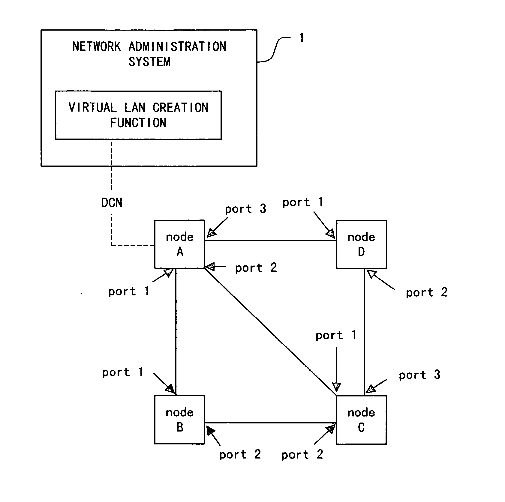
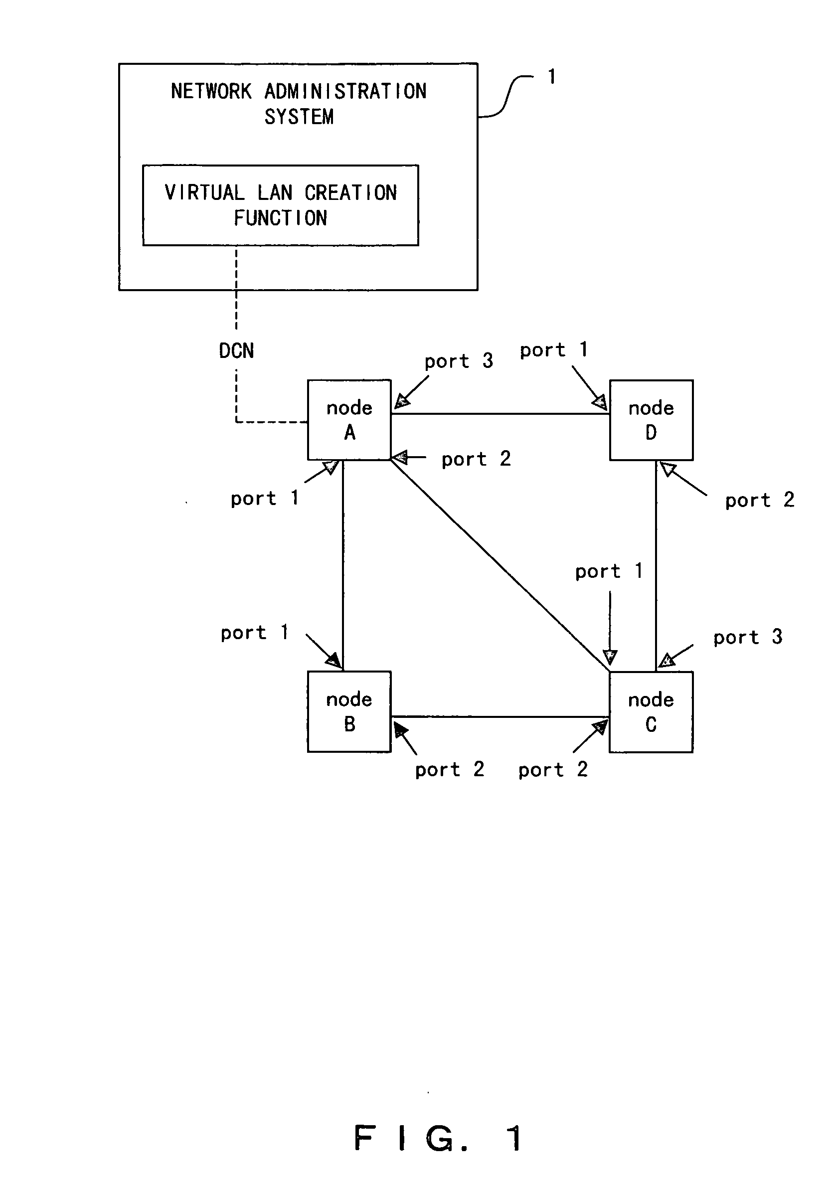
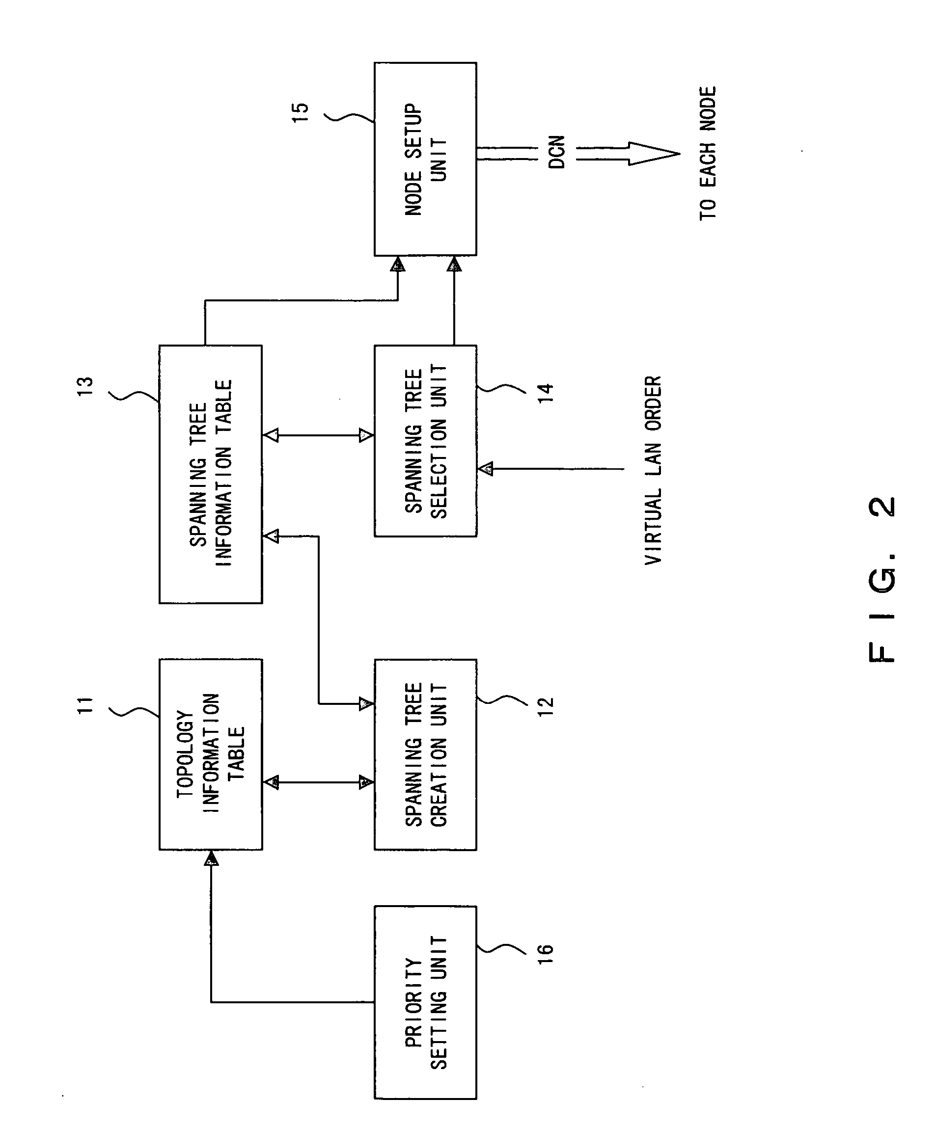
[0142] A network administration system 1 according to a first embodiment comprises a priority setting unit 16 for attaching a priority level to each of the links between nodes. Here, the priority setting unit 16 sets the priority level of each link, for example, according to the instructions from the network administrator. Then, a spanning tree creation unit 12 creates a plurality of spanning trees in reference to the link priority level.

[0143]FIG. 15 is a diagram showing a configuration of a topology information table 11 according to the first embodiment. In FIG. 15, the bandwidths, transmission delay time, and usage costs are, for example, stored as the “parameter”. In addition, the parameter regarding priority level is set as a “priority level flag” by the priority setting unit 16.

[0144] When the network administration system 1 is booted, the priority setting unit 16 determines the priority level flag of each link in the topology information table 11 shown in FIG. 15. For examp...

second embodiment

[0173] Spanning tree creation unit 12 comprised in the network administration system 1 in a second embodiment takes into consideration the number of times each link has been used, respectively, to create a spanning tree, when creating a plurality of spanning trees.

[0174]FIG. 24A is a diagram showing a configuration of the topology information table 11 in the second embodiment. Here, bandwidth is stored, respectively, as the “parameter” for each link, and the “priority level flag” of each link is determined based on this parameter. The “priority level flag” is, for example, set by the priority setting unit 16, as explained in the first embodiment. In addition, the topology information table 11 in the second embodiment manages the “link selection count” which indicates the number of times each link has been selected, respectively, to create a spanning tree.

[0175] The spanning tree creation unit 12 refers to the topology information table 11 when creating a plurality of spanning tree...

third embodiment

[0185] In a third embodiment, when selecting the spanning tree to which the requested virtual LAN is mapped out of a plurality of spanning trees created beforehand, the spanning tree with the smallest number of links in its path is selected in a case where the virtual LAN is mapped. In other words, the spanning tree with the smallest total hop count in the path the virtual LAN traffic flows through is selected.

[0186]FIG. 27 is an example of the topology information table 11 in the third embodiment. Here, “bandwidth” refers to link bandwidth. In addition, “bandwidth in use” is the bandwidth which is currently and actually being used, or bandwidth which is already assigned to the virtual LAN. For example, the record in the first line of this table indicates that the link cost between nodes A and B is “10”, the bandwidth is “5”, and the bandwidth being used is “0.5”. The unit for “bandwidth” and “bandwidth in use” is, for example, “Mbps”.

[0187]“Bandwidth in use” is updated by the net...


PUM


Abstract

A spanning tree creation unit creates a plurality of spanning trees based on the network topology, and registers the spanning trees to a spanning tree information table. A spanning tree selection unit selects a spanning tree wherein communication resources will be used most effectively, out of the plurality of spanning trees registered to the spanning tree information table. A node setup unit sets the mapping information which expresses correspondence between the requested virtual LAN and the selected spanning tree in each node.

Description

CROSS REFERENCE TO THE RELATED APPLICATION [0001] This application is a continuation of International Application PCT / JP03 / 01797, which was filed on Feb. 19, 2003.BACKGROUND OF THE INVENTION [0002] 1. Field of the Invention [0003] The present invention relates to a device and method for creating a virtual LAN and a network system which provides virtual LAN services. In particular, this present invention relates to a device and method for creating virtual LAN implementing the multiple spanning tree protocol and a network system which provides virtual LAN services implementing the multiple spanning tree protocol. [0004] 2. Description of the Related Art [0005] In recent years, due to the implementation of the Gigabit-class Ethernet (registered trademark) technology standardized by the IEEE, virtual LAN (VLAN) services which utilize Ethernet over a comparably wide area and services providing virtual private networks (VPN) are receiving attention. In addition, communication networks for...

Claims


Application Information

Patent Timeline
Patent Type & Authority Applications(United States)
IPC IPC(8): H04L12/44H04L12/46
CPCH04L12/462H04L45/48H04L45/02H04L12/4641H04L45/484H04L45/488
Inventor NAGATA, AKIRACHUGO, AKIRAMIYAZAKI, KEIJIUENO, HITOSHISUGITA, KIYOSHIONODERA, TAKASHIOHASHI, MASAHIKO
Owner FUJITSU LTD
Why Eureka
Try Eureka