

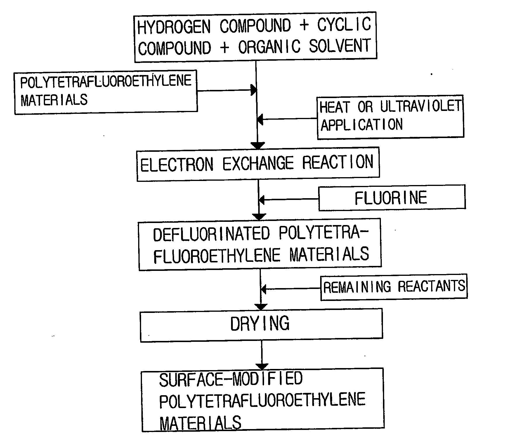
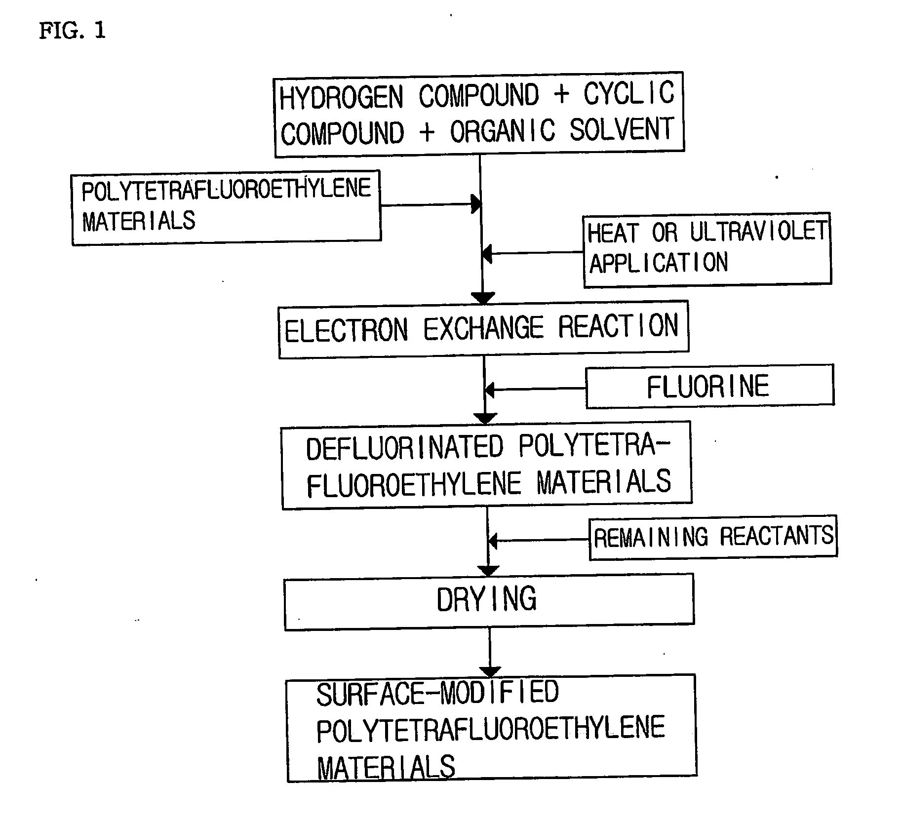
Method of chemical surface modification of polytetrafluoroethylene materials
a technology of polytetrafluoroethylene and surface modification, which is applied in the direction of gas-gas reaction process, prosthesis, blood vessel, etc., can solve the problems of unstable industrial application, unstable surface of micropores, and inability to modify the surface of micropores, etc., to improve the biocompatibility of polytetrafluoroethylene materials.
- Summary
- Abstract
- Description
- Claims
- Application Information
AI Technical Summary
Benefits of technology
Problems solved by technology
Method used
Image

Examples
example 1
Surface Modification of Expanded Polytetrafluoroethylene Artificial Blood Vessel
[0063] 0.4 g of sodium hydroborate, 0.8 g of anthraquinone, and 100 ml of anhydrous dimethylformamide were introduced into a 250 ml round flask.
[0064] The mixture was stirred using a magnetic stirring bar, thereby producing a reactant solution.
[0065] A polytetrafluoroethylene artificial blood vessel of a 5 cm length was introduced in the reactant solution.
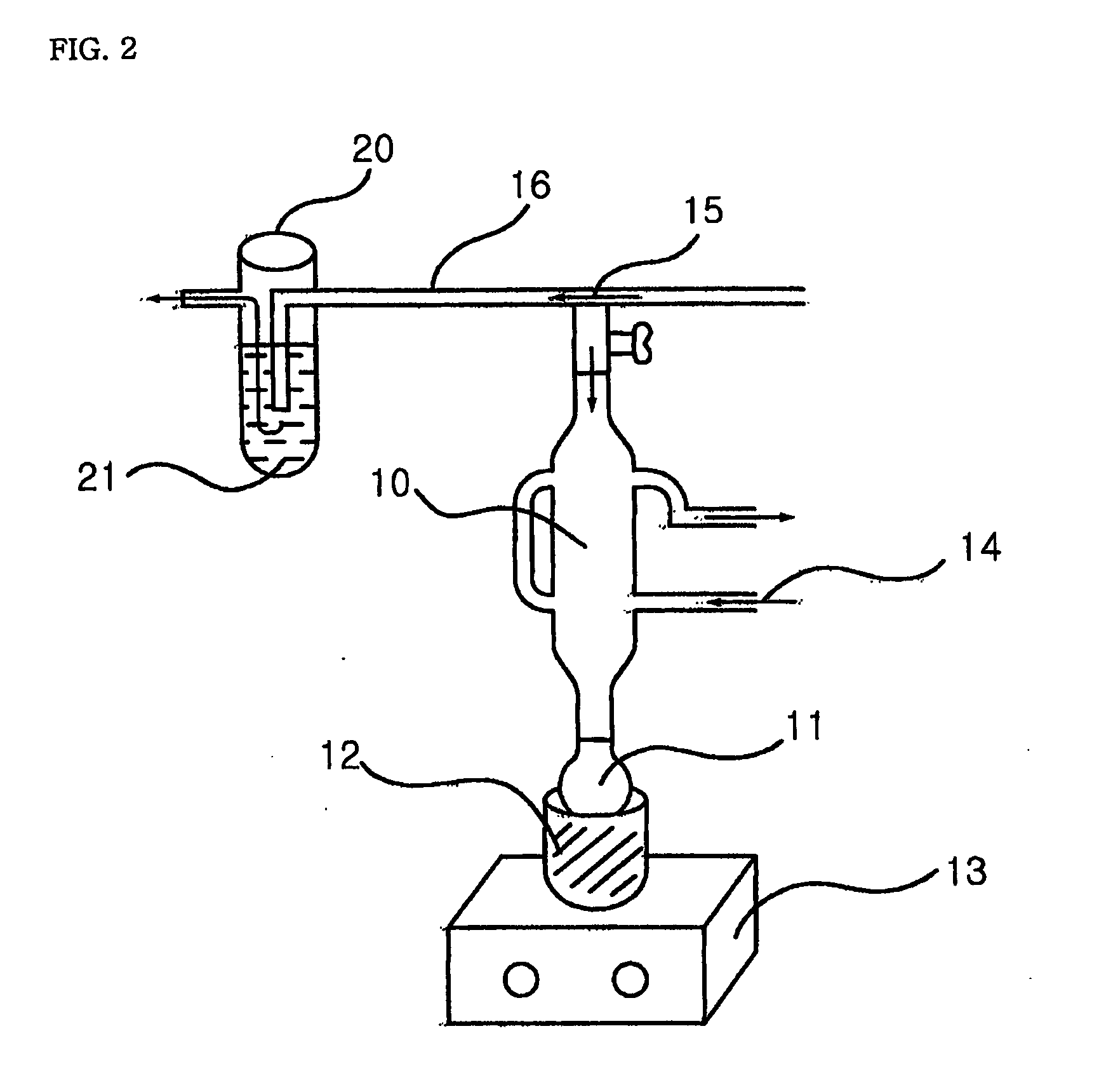
[0066] A reaction apparatus was set as shown in FIG. 2.
[0067] The round flask containing the reactant solution and the ePTFE artificial blood vessel was connected to a condenser, and a hose was connected to a port disposed at the outside of the condenser such that water could be circulated.
[0068] A gas line connected to a nitrogen line was connected to the upper portion of the condenser connected to the round flask. After this, using a mantle and a controller, the reactant solution was electrically heated to 100° C. with nitrogen passed therethrou...
example 2
Surface Modification of ePTFE Artificial Blood Vessel for 48 Hours
[0074] The surface of an ePTFE artificial blood vessel was modified in the same manner as Example 1 except that the reaction was carried out for 48 hours instead of reacting for 24 hours.
example 3
Surface Modification of ePTFE Artificial Blood Vessel for 72 Hours
[0075] The surface of an ePTFE artificial blood vessel was modified in the same manner as Example 1 except that the reaction was carried out for 72 hours instead of reacting for 24 hours.
PUM
| Property | Measurement | Unit |
|---|---|---|
| Temperature | aaaaa | aaaaa |
| Time | aaaaa | aaaaa |
| Energy | aaaaa | aaaaa |
Abstract
Description
Claims
Application Information