Pain measurement system and method of measuring pain

a measurement system and pain technology, applied in the field of pain measurement system and pain measurement method, can solve the problems of difficult comparison of pain measured magnitudes between different patients, difficulty in properly expressing pain magnitude, and failure to achieve the effect of reducing irregularity and reducing irregularity

Active Publication Date: 2005-07-14
TERUMO KK
View PDF7 Cites 11 Cited by
  • Summary
  • Abstract
  • Description
  • Claims
  • Application Information

AI Technical Summary

Benefits of technology

[0038] In the first measuring process, the magnitude of the stimulus applied by the stimulus applying means may increase stepwise, and an increase per step in the magnitude of the stimulus and the time during which the magnitude of the stimulus may persist in each step increase and decrease irregularity.
[0039] In the second measuring process, the magnitude of the stimulus applied by the stimulus applying means may increase stepwise, and an increase per step in the magnitude of the stimulus and the time during which the magnitude of the stimulus may persist in each step increase and decrease irregularity.

Problems solved by technology

However, it is difficult to properly express magnitudes of pain because the sensation of pain is subjective and personal, and the degree to which one can tolerate pain is easily affected by cultural and psychological factors.
Although the above evaluating method is simple, it is subjective and has evaluation standards varying from patient to patient.
This makes it difficult to compare measured magnitudes of pain between different patients.
However, those efforts have proven unsuccessful.

Method used


Image

  • Pain measurement system and method of measuring pain
  • Pain measurement system and method of measuring pain
  • Pain measurement system and method of measuring pain

Examples


first embodiment

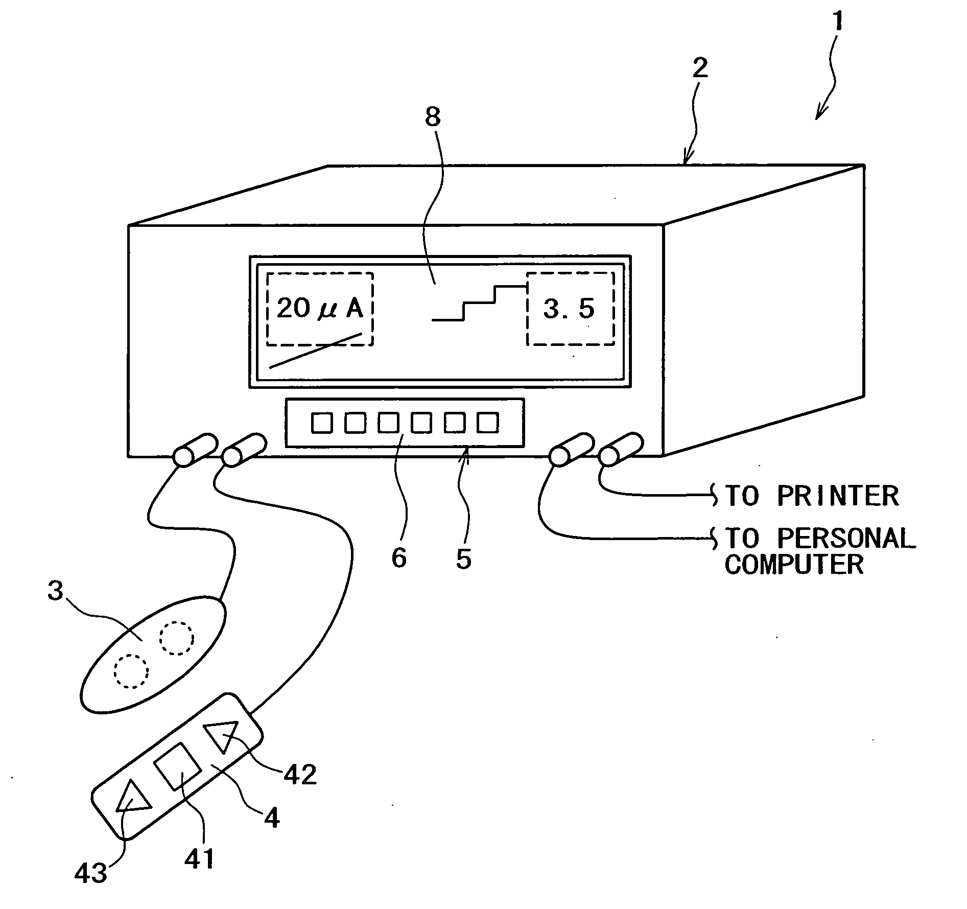
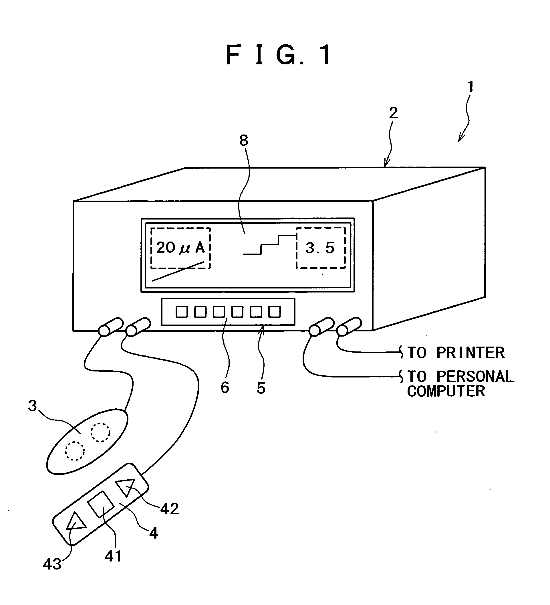
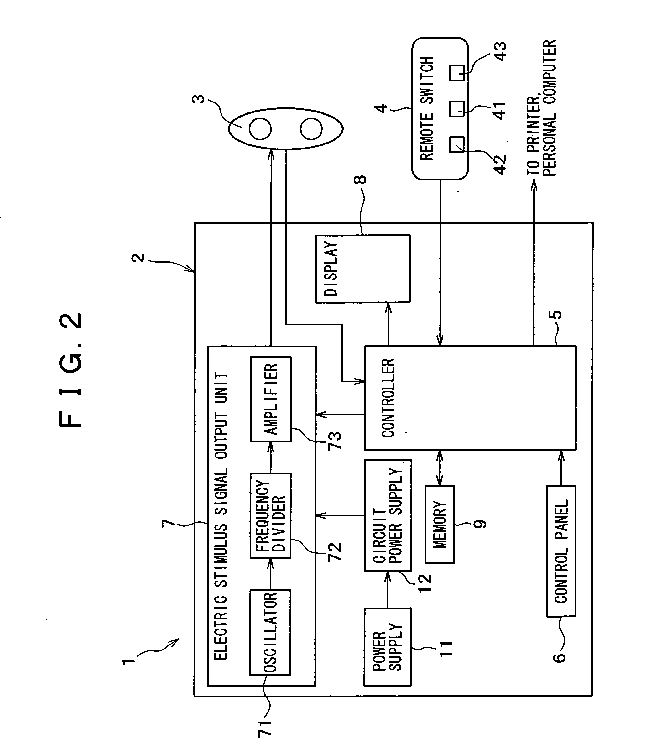
[0062] A pain measurement system 1 according to the present invention as shown in FIGS. 1 through 3 applies an electric stimulus (an electric stimulative sensation), particularly a painless electric stimulus (painless stimulus), which is different from pain experienced by a patient (examinee). The system 1 compares the magnitude of the electric stimulus and the magnitude of actual pain (measured pain) to quantify the magnitude of the pain in the patient.

[0063] When a certain electric stimulus (a current under certain conditions) is applied to a patient, the patient develops a painless sensation such as a numb sensation (vibratory sensation). When the electric stimulus, i.e., the magnitude of the current, increases or decreases, the magnitude of the sensation developed by the patient also increases or decreases. Therefore, the magnitude of pain can be measured without having the patient feel pain due to the measurement, by comparing the magnitude of the electric stimulus (the sensati...

second embodiment

[0157] A pain measurement system according to the present invention will be described below.

[0158]FIG. 7 is a diagram illustrative of the manner in which the pain measurement system according to the second embodiment of the present invention operates.

[0159] The pain measurement system, also denoted by 1, according to the second embodiment will be described below basically with respect to differences with the pain measurement system according to the first embodiment. Those details of the pain measurement system 1 according to the second embodiment which are the same as the pain measurement system according to the first embodiment will not be described in detail below. The pain measurement system 1 according to the second embodiment operates in the third step as follows: In the step-up control mode, the current value of a pulse current (the magnitude of a stimulus) increases stepwise by nX, and the time during which it stays in each step changes, and in the step-down control mode, th...

third embodiment

[0164] A pain measurement system according to the present invention will be described below.

[0165]FIG. 8 is a diagram illustrative of the manner in which the pain measurement system according to the third embodiment of the present invention operates.

[0166] The pain measurement system, also denoted by 1, according to the third embodiment will be described below basically with respect to differences with the pain measurement system according to the first embodiment. Those details of the pain measurement system 1 according to the third embodiment which are the same as the pain measurement system according to the first embodiment will not be described in detail below.

[0167] The pain measurement system 1 according to the third embodiment performs a measuring process at least twice.

[0168] For example, if the pain measurement system 1 performs a measuring process twice, then, in the first measuring process, the current value of a pulse current increases at a substantially constant rate ...


PUM


Abstract

A pain measurement system is capable of accurately and reliably measuring the magnitude of temporary pain in a patient while reducing burdens on the patient during pain measurement. The pain measurement system has a system assembly including a controller and an electric stimulus signal output unit, an electrode, and a remote switch. The controller controls the electric stimulus signal output unit to apply a pulse current which increases with time through the electrode. The value of the pulse current is recognized as a minimum sensed current value when a first signal is received. The electric stimulus signal output unit is then controlled to apply, through the electrode, a pulse current having a current value which increases from a predetermined initial value stepwise by nX (where X represents the minimum sensed current value and n represents a positive rational number). The current value of the pulse current is recognized as a pain-commensurate current value when a second signal is received.

Description

BACKGROUND OF THE INVENTION [0001] 1. Field of the Invention [0002] The present invention relates to a pain measurement system and a method of measuring pain. [0003] 2. Description of the Related Art [0004] Pain can be described generally in two ways. According to one approach, pain is expressed in terms of quality or type. For example, pain may be described as “burning pain”, “smarting pain”, “pricking pain”, etc. The other way of describing pain is based on the magnitude of pain. For example, pain may be described as “slight pain”, “unbearable pain”, etc. [0005] The former pain expressions can easily be made if one is aware of a certain range of modifying words for pain. However, it is difficult to properly express magnitudes of pain because the sensation of pain is subjective and personal, and the degree to which one can tolerate pain is easily affected by cultural and psychological factors. [0006] Nevertheless, an objective evaluation of pain is indispensable for diagnosing pain...

Claims


Application Information

Patent Timeline
Patent Type & Authority Applications(United States)
IPC IPC(8): A61B5/05A61B5/103A61B10/00
CPCA61B5/4824
Inventor SHIMAZU, HIDEAKIISHII, TAKEO
Owner TERUMO KK
Why Eureka
Try Eureka