Power distribution/generation system

a power distribution and generation system technology, applied in the direction of lighting and heating equipment, process and machine control, instruments, etc., can solve the problems of customers losing power for hours, days or even weeks at a time, and certain inconveniences,

Inactive Publication Date: 2005-07-14
MICROGEN ENERGY
View PDF8 Cites 94 Cited by
  • Summary
  • Abstract
  • Description
  • Claims
  • Application Information

AI Technical Summary

Benefits of technology

[0010] Pursuant to the foregoing objectives, the present invention comprises a method and system in which one or more electric power generators are located at or near a consumer's premises, to provide power which is dedicated to the needs of that consumer. In one embodiment of the invention, the power provided by the on-site generators complements that which is delivered via a centralized power grid network. For example, the on-site generators can be normally configured to provide power to critical components of the consu...

Problems solved by technology

From the standpoint of the customer, certain inconveniences are associated with the concentration of power distribution in a single entity.
Catastrophic weather conditions, such as hurricanes, tornadoes, ice storms, and the like, can severely disrupt the power distribution facilities, causing customers to lose access to power for hours, days or even weeks at a time.
Increasingly volatile weather patterns have exacerbated this problem.
Power reliability is also adversely impacted by construction and motor vehicle accidents that disrupt power lines.
As a result, the amount of power delivered to each customer is reduced, resulting in so-called “brown-out” conditions.
Under these conditions, certain types of equipment may not operate properly, or may fail to operate at all, due to voltage levels that are below minimum specifications, and/or fluctuations that are created by an electrical utility in balancing of loads.
This problem becomes more acute with the increasing use of various types of low-power digital electronic equipment, such as computers, which are much more sensitive to variations in voltage levels.
Frequent fluctuations in power quality such as dips, surges, sags and spikes are a significant source of annoyance and disruption to consumers.
These and other power quality inconsistencies are driven mainly by the factors described above: weather, accidents and grid congestion.
Another source of inconvenience associated with centralized power distribution is the unpredictability of cos...

Method used


Image

  • Power distribution/generation system
  • Power distribution/generation system
  • Power distribution/generation system

Examples


Embodiment Construction

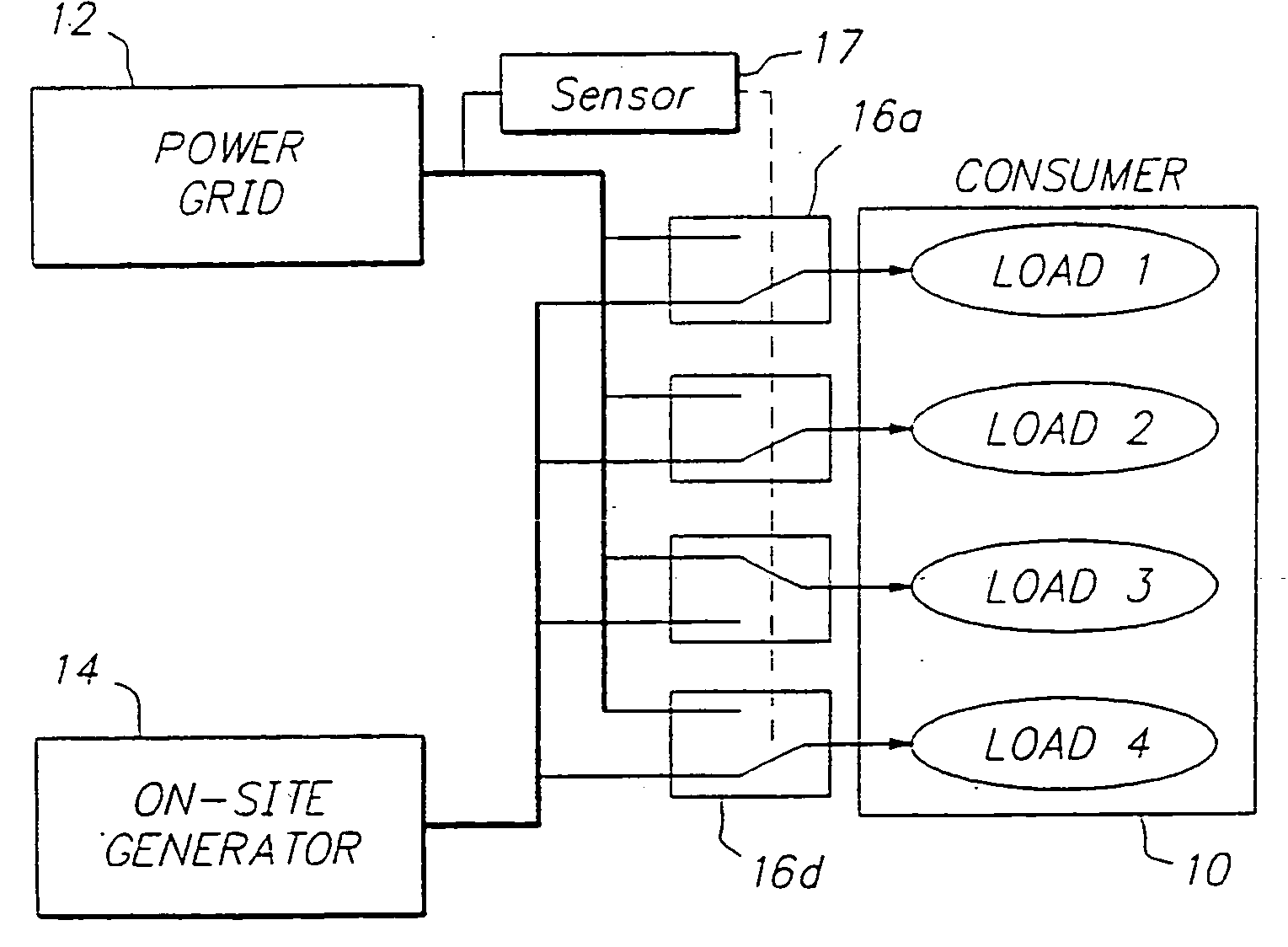
[0020] Generally speaking, the present invention is directed to an arrangement in which power generation equipment is located at the site of a consumer, and provides electrical power that supplements and / or replaces the power delivered by a centralized power distribution network, such as those affiliated with regional power utilities. To facilitate an understanding of the invention, it will be described hereinafter with reference to its use in connection with the power requirements of commercial enterprises and light industry. It will be appreciated, however, that the practical implementations of the invention are not limited to these particular applications. Rather, in view of the reliability and economic advantages offered by the invention, it can be used by all types of electrical power consumers.

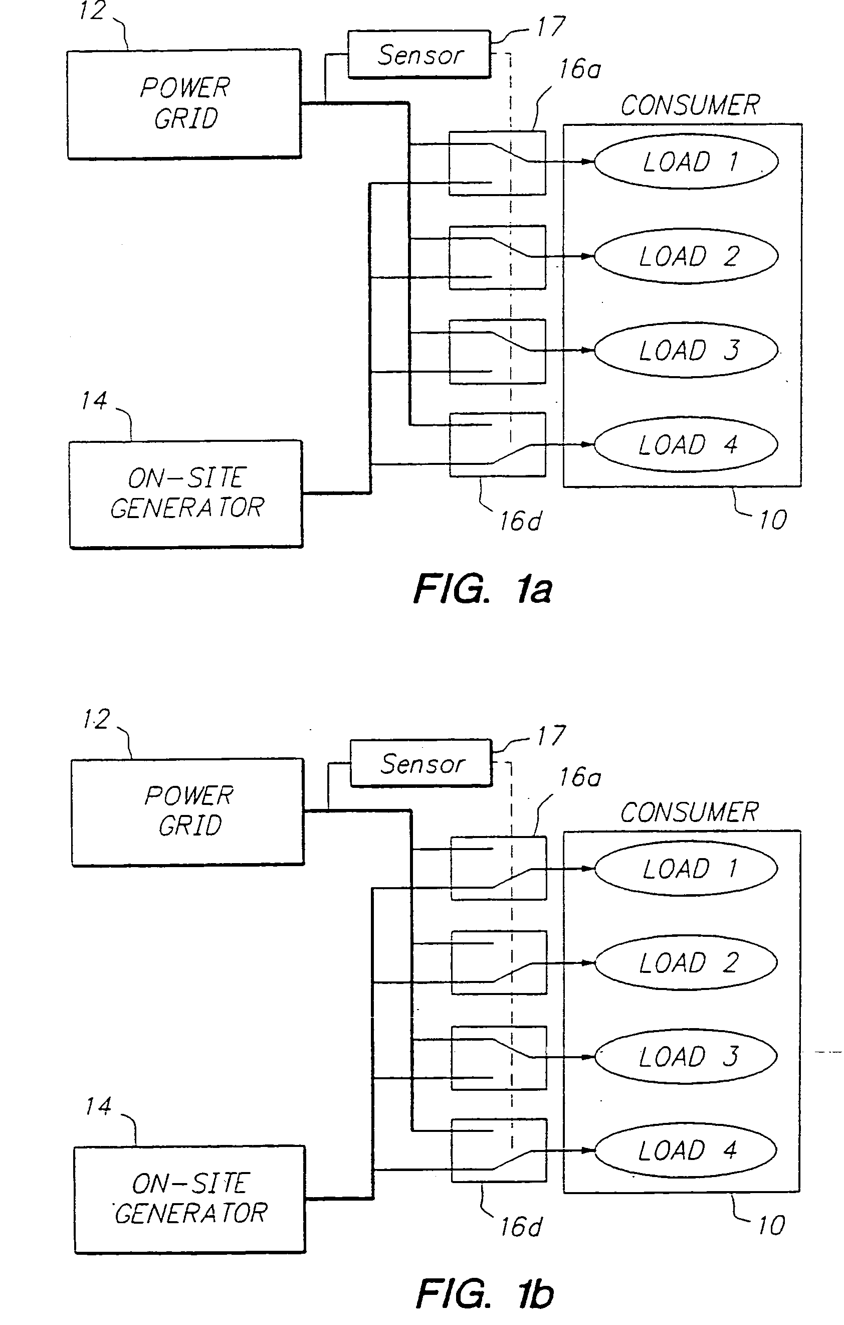
[0021] A simplified overview of one implementation of the invention is illustrated in'the block diagram of FIG. 1a. An electrical power consumer 10 may have a number of different type...


PUM


Abstract

A power distribution/generation system is disclosed for supplying electrical power to a number of sites (32, 33, 34), one or more of which has a generator (53, 1) such as a Stirling engine (1) which is capable of generating electrical power. The generators (53, 1) are linked together on a local network that is connectable to an external power grid (31). A controller (35) can hold the distribution of power so that a site is supplied with electrical power from the local network if its power demand exceeds the power generated by the generators in that network. However, if the total power demand of all the sites in the network exceeds the total power available from the generators in that network, then the controller (35) causes power to be drawn from the grid (31) instead.

Description

FIELD OF THE INVENTION [0001] The present invention is directed to the delivery of energy to consumers, and more particularly to a system which integrates on-site energy generation capabilities with conventional centralized power distribution networks. BACKGROUND OF THE INVENTION [0002] Conventionally, the delivery of various types of energy to consumers, such as industries, commercial entities, and residential customers, has been carried out by regulated agencies. For example, in the United States the distribution of electrical power has been serviced by a few thousand regulated monopoly franchises. In many cases, all of the energy customers within a given geographic area rely upon a single electrical power distribution company for their entire supply. [0003] From the standpoint of the customer, certain inconveniences are associated with the concentration of power distribution in a single entity. Foremost among these is the reliability with which the power is delivered. The ability...

Claims


Application Information

Patent Timeline
IPC IPC(8): F02G1/043F02G5/00F24D18/00H02J3/38
CPCF02G1/043F02G5/00F24D2200/04Y02T10/166H02J3/38Y02E20/14F24H2240/04Y02T10/12F24D18/00F24D2101/80
Inventor ALDRIDGE, WAYNE KENNETHCLARK, DAVID ANTHONYCOOPER, JAMES EDWARDALLDERIDGE, HEATHERROBERTS, GRAHAM RICHARD
Owner MICROGEN ENERGY
Why Eureka
Try Eureka