
Vehicle occupant classification system and method

Inactive Publication Date: 2005-07-14
WALLACE MICHAEL W
View PDF19 Cites 14 Cited by
  • Summary
  • Abstract
  • Description
  • Claims
  • Application Information

AI Technical Summary

Benefits of technology

[0020] One object of the present invention is to enable a vehicle occupant detection system to classify vehicle occupants accurately.
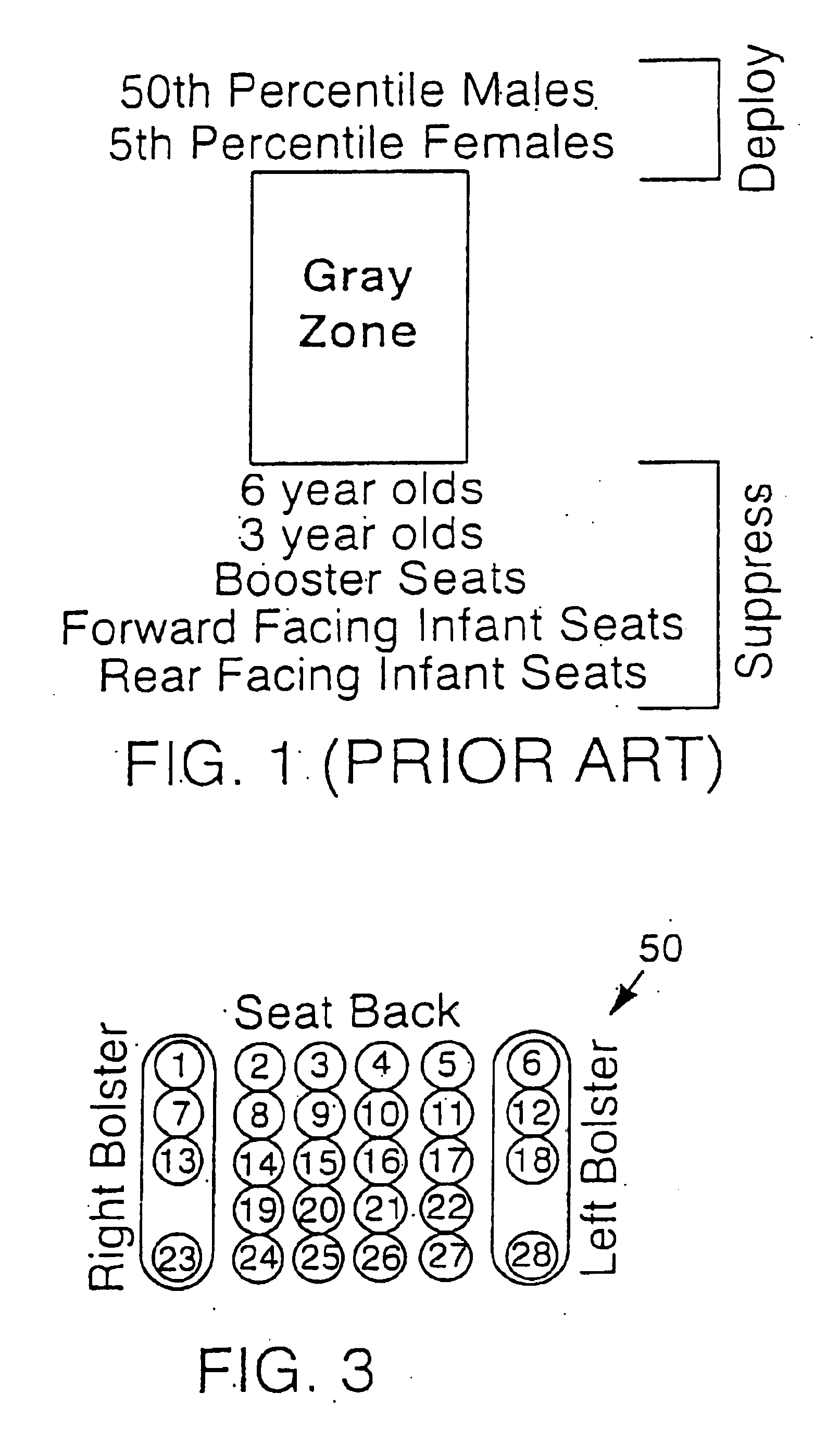
[0021] Another object of the present invention is to enable a vehicle occupant detection system to distinguish accurately between 5th Percentile Females and 6-Year Olds.
[0022] Another object of the present invention is to provide an airbag deployment system that makes a suppress or deploy decision based on an accurate identification of a vehicle occupant.

Problems solved by technology

Unfortunately, the force and speed requirements to save 180 lb. males are tremendous, and present a potentially fatal hazard to young children (especially when seated in rear-facing infant seats) and to small females.
There is also a significant danger of physical injury or death from airbag deployment for anyone who is situated too close to the dashboard / steering column or who is otherwise in a vulnerable position during deployment.
In other words, it is very hard to distinguish between 5th Percentile Females and 6-Year Olds based on their in-seat weight or pattern characteristics.
Unfortunately, however, as the following table, Table 1, illustrates, distinguishing between these occupant categories is a very challenging undertaking.
The similarity between these occupant-types in their typical in-seat weights makes it extremely difficult to classify them based solely on this characteristic.
The problem of accurately classifying an occupant based on his or her in-seat weight is compounded as the occupant moves in the seat.
Clothing friction against the seat back and the angle of inclination of the seat back can also affect the amount of weight exerted in the seat.
All of these factors make the in-seat weight of an occupant insufficient as a sole source of information for occupant detection.
Unfortunately, the IEE FSR is notoriously difficult to use and suffers from a high degree of variation in production.
Seat foam typically exhibits a memory, however, and therefore isn't an ideal mechanical medium for a deflection sensor without its own spring system.
Unfortunately, this system is only able to approximate weight in the seat and cannot reliably distinguish between 6-Year Olds and 5th Percentile Females.
It also cannot accurately classify tightly belted child seats in static (without vehicle motion) situations.
Accordingly, although not reliable for static situations, these systems can be used to satisfy some of the goals of occupant detection.
Unfortunately, these seat frame systems can only estimate occupant weight based on the weight exerted in the seat.
Furthermore, the presence of floor-anchored seat belts complicates decisions for these systems.
In other words, the closer the occupant is positioned to the airbag, the greater the risk of injury from its deployment.
A drawback of proximity detection systems is that they generally have difficulty making the appropriate deployment decision when books, pillows, newspapers, or other objects are held in front of the occupant.
Proximity detection systems also frequently have difficulty detecting child seats.
Unfortunately, no one has yet been able to provide a hardware / software combination capable of meeting all of the NHTSA's proposed requirements.
None of the known occupant detection systems currently in existence are able to accurately distinguish between 5th Percentile Females and 6-Year Olds.

Method used


Image

  • Vehicle occupant classification system and method
  • Vehicle occupant classification system and method
  • Vehicle occupant classification system and method

Examples


Embodiment Construction

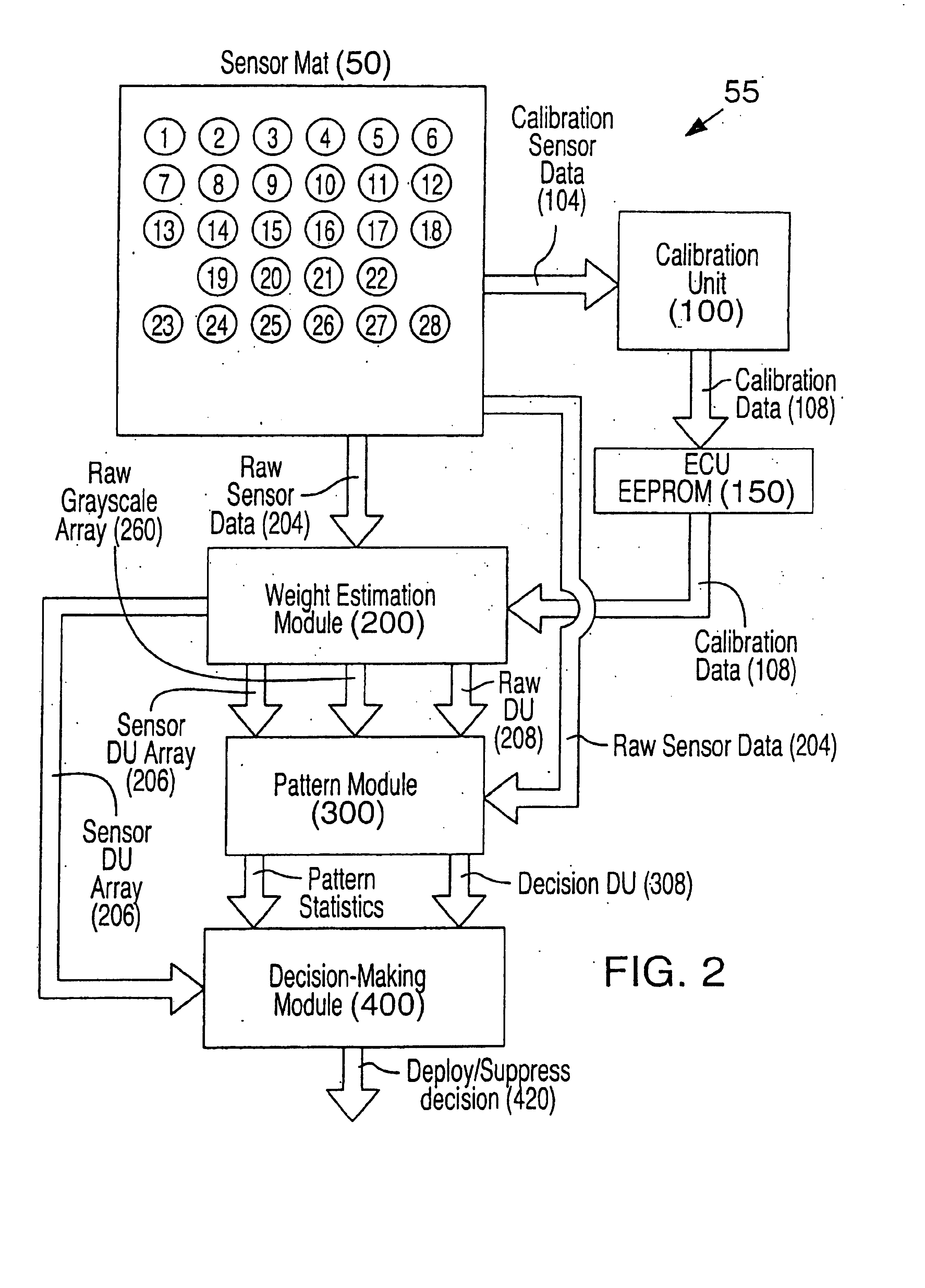
[0078]FIG. 2 is a block diagram illustrating the major components of the Vehicle Occupant Classification System (classification system) 55 according to a preferred embodiment of this invention. The classification system 55 combines weight estimation, pattern recognition, and statistical evaluation of in-seat characteristics of an occupant in order to make an informed airbag deployment state decision. Referring to FIG. 2, the major components of the classification system include a Calibration Unit 100, a Weight Estimation Module 200, a Pattern Module 300, and a Decision-Making Module 400. Using these three components, the classification system of this invention is able to accurately detect a vehicle occupant and appropriately determine a proper airbag deployment state based on that occupant's in-seat characteristics.

[0079] The Calibration Unit 100 receives sensor data from a sensor mat50, located in the vehicle seat, during a calibration process. The purpose of the calibration proce...


PUM


Abstract

A vehicle occupant classification system classifies a vehicle occupant based on data from an array of sensors using a combination of weight estimation, pattern recognition, and evaluation of statistical characteristics. This occupant classification can then be used to make an airbag deployment state decision. The major modules of this system can include a calibration unit, a weight estimation module, a pattern module, and a decision-making module. The calibration unit can perform a calibration process to normalize sensor deflections using a known deflection force in order to compensate for variations in sensors and the effects of the seat trim and foam. The weight estimation module can perform a weight estimation process that uses calibration data from the calibration process and sensor data from the sensors to translate sensor deflection due to a vehicle occupant into a displacement value. The pattern module can look for traits in the pattern of sensor deflections that are common for objects other than people. Finally, the decision-making module can make a deployment state decision for the airbag by looking at displacement trends to evaluate occupant weight and movement, and by evaluating pattern information.

Description

[0001] This application is a divisional of U.S. patent application Ser. No. 09 / 853,848, filed on May 10, 2001, now pending, both of which claim priority from U.S. Provisional Application Ser. No. 60 / 203,001, filed May 10, 2000, herein incorporated by reference.BACKGROUND OF THE INVENTION [0002] This invention relates generally to systems and methods for detecting the occupants of an automobile. More specifically, this invention relates to weight-based and pattern-based automobile occupant detection systems and to methods and systems for making airbag deployment decisions based on information received from an occupant detection system. [0003] In the United States, airbag deployment forces and speeds have been optimized to save 180 lb. males. Unfortunately, the force and speed requirements to save 180 lb. males are tremendous, and present a potentially fatal hazard to young children (especially when seated in rear-facing infant seats) and to small females. There is also a significant ...

Claims


Application Information

Patent Timeline
IPC IPC(8): B60R21/01B60R21/015G06K9/00
CPCG06K9/00362B60R21/0154B60R21/01516G06V40/10
Inventor WALLACE, MICHAEL W.
Owner WALLACE MICHAEL W
Learn More