
ExpressCard power switch device with enhanced communications paths and security functions

a technology of security functions and power switches, applied in the direction of power supply for data processing, instruments, computing, etc., can solve the problems of difficult management of bios level code, prone to errors, and inability to function properly withou

Inactive Publication Date: 2005-07-14
MAISHI ELECTRONICS (SHANGHAI) LTD
View PDF3 Cites 22 Cited by
  • Summary
  • Abstract
  • Description
  • Claims
  • Application Information

AI Technical Summary

Benefits of technology

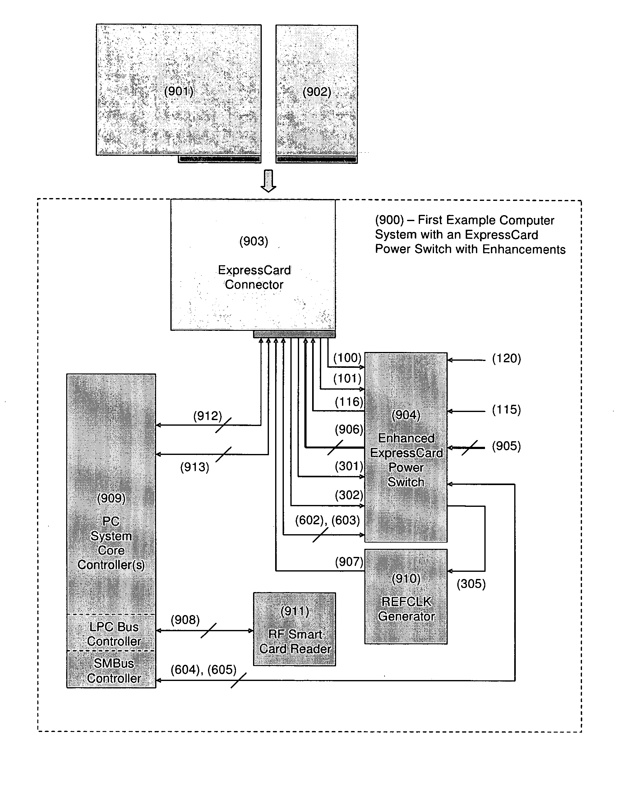
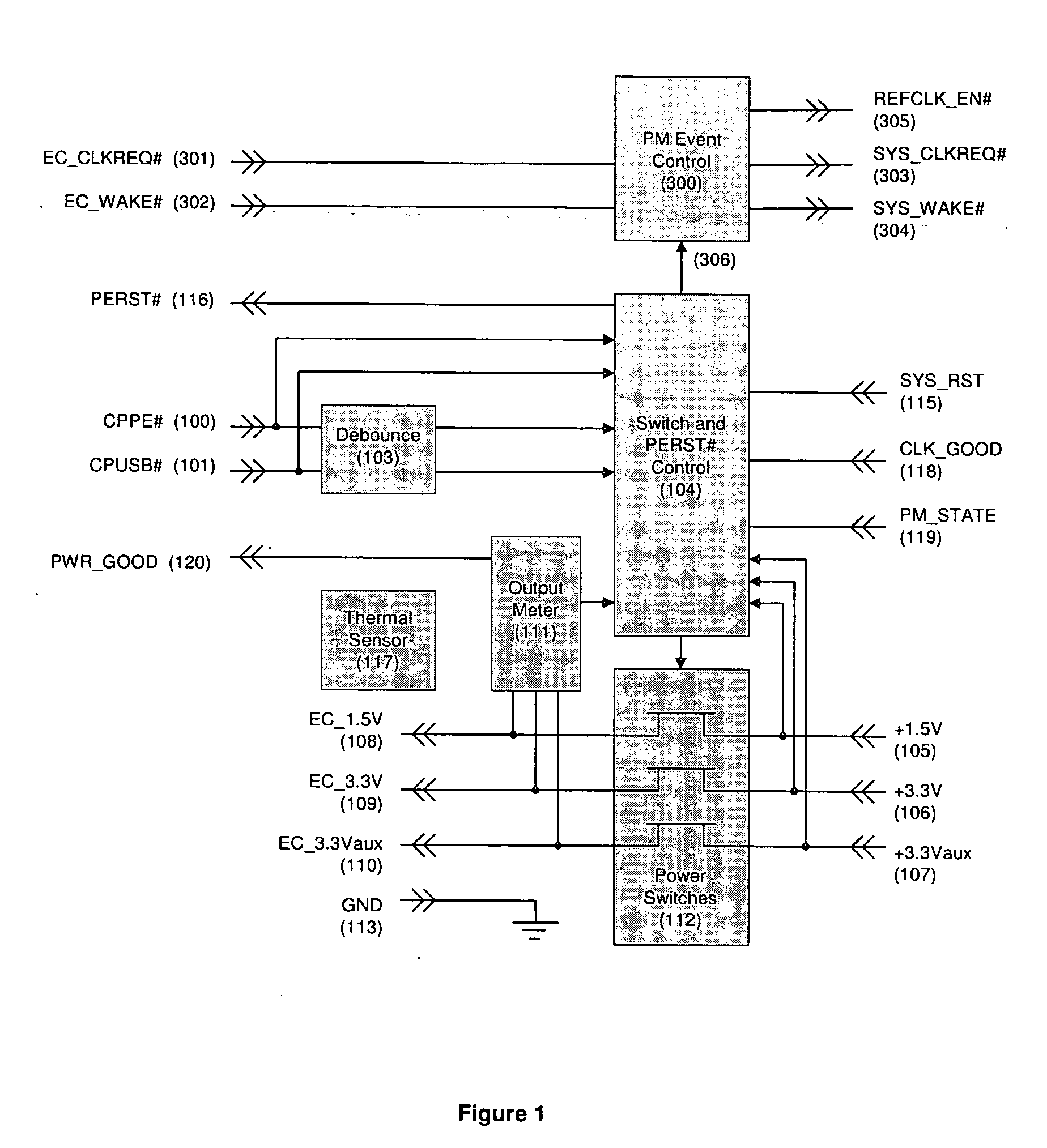
[0044]FIG. 1 illustrates a view of an enhanced ExpressCard power switch block diagram, including input terminals for ExpressCard WAKE# and CLKREQ# signals, and a circuit to control power management events associated with these new inputs;
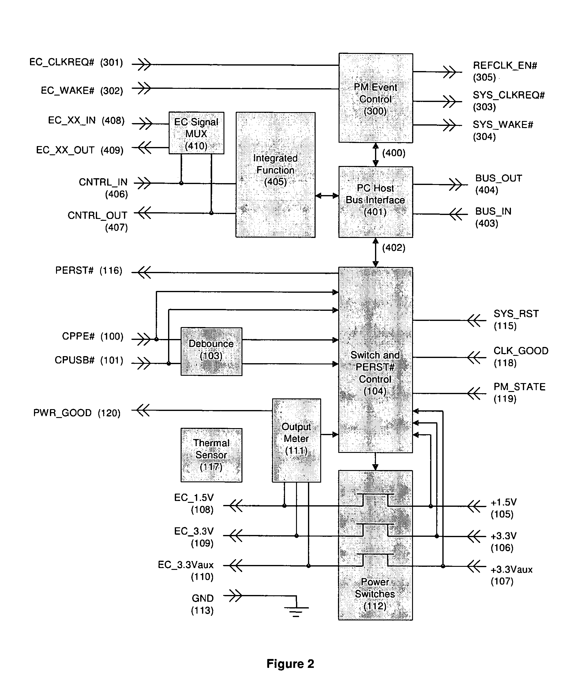
[0045]FIG. 2 illustrates a view of...

Problems solved by technology

BIOS level code is difficult to manage across several computer system vendors, and is prone to error with lack of specification, and generally not as upgradeable as a typical software component (e.g. peripheral device driver).
Although optional, many SMBus devices include these signals in their terminal map, and may not function properly without them.
Further inadequacy is found in that SMBus is not conventionally a hot-plug capable interface, and more careful design is required for a computer system to operate within predictable boundaries.
Although USB and PCI Express are functionally capable of providing many conventional applications, there may be an increased cost of the modules by limiting the electrical interfaces.

Method used


Image

  • ExpressCard power switch device with enhanced communications paths and security functions
  • ExpressCard power switch device with enhanced communications paths and security functions
  • ExpressCard power switch device with enhanced communications paths and security functions

Examples


Embodiment Construction

[0052]FIG. 1 illustrates one exemplary block diagram of an enhanced ExpressCard power switch according to one embodiment. The ExpressCard power switch according to this embodiment may include power switches (112) which may meet the electrical specifications and the recommended on-resistance ranges provided in the aforementioned Guidelines. The power switches (112) may pass a first primary +1.5V power source (105), a second primary +3.3V power source (106), and a first auxiliary power source (107) to the ExpressCard module (not shown), typically via conventional field effect transistor (FET) techniques. When connected, the power switches (112) may provide the corresponding voltage level to the corresponding ExpressCard module power terminals, that is, the +1.5V supply signals (108), the +3.3V supply signals (109), and the +3.3Vaux supply signals (110). Conventionally, when the power switches are not connected, either a high impedance state may be presented to the ExpressCard module p...


PUM


Abstract

A method according to one embodiment includes receiving at least one ExpressCard module power management signal and controlling the passing of at least one ExpressCard power management signal to a host computer system, based on, at least in part, at least one signal indicative of a power state of the host computer system. Of course, many alternatives, variations, and modifications are possible without departing from this embodiment.

Description

[0001] This application claims priority to U.S. Provisional Application Ser. No. 60 / 529,290 filed Dec. 12, 2003, the teachings of which are hereby incorporated by reference in its entirety.FIELD OF INVENTION [0002] This disclosure relates to the design and manufacturing of power switch circuits that interface to ExpressCard sockets. BACKGROUND OF THE INVENTION [0003] The PCMCIA organization has developed specifications and implementation guidelines for a new type f PC Card called an ExpressCard. ExpressCard™ is a trademark of PCMCIA organization. The ExpressCard has a new form factor and electrical interface, and does not support the PCMCIA 16-bit or 32-bit (CardBus) interfaces defined by previous PC Card Standards. [0004] The ExpressCard technical details are specified by PCMCIA Proposal 279, soon to be published, and in draft version 1.00 review. The “NEWCARD_Draft—1.0-091003” (Sep. 10, 2003) Electromechanical Specification and the “Guidelines_Draft—0.95110703” Implementation Guid...

Claims


Application Information

Patent Timeline
IPC IPC(8): G06FG06F1/26G06F1/32
CPCG06F1/3203G06F1/26
Inventor MORROW, NEIL
Owner MAISHI ELECTRONICS (SHANGHAI) LTD
Learn More