
Efficient battery powered electronic parking meter

a technology of electronic parking meters and battery packs, which is applied in the direction of paper-money testing devices, ticket-issuers, coin/paper handlers, etc., can solve the problems of battery power storage capacity and the number of constraints on the powering of parking meters, and achieve the effect of improving the visibility of parking related messages

Inactive Publication Date: 2005-07-21
J J MACKAY CANDADA
View PDF14 Cites 74 Cited by
  • Summary
  • Abstract
  • Description
  • Claims
  • Application Information

AI Technical Summary

Benefits of technology

[0010] In accordance with a further aspect of this invention, the output interface comprises one or more LCD's adapted to display parking related messages. The LCD's may have a front LCD and a back LCD having a number of similar or different message elements that are controlled by the microcontroller, the microcontroller includes paging units for controlling the activation of the parking related messages on the LCD's individually in ON / OFF or blinking modes. A backlight may be positioned relative to the front and the back LCD's to enhance the visibility of the parking related messages

Problems solved by technology

The requirements of parking authorities place a number of constraints on the powering of the parking meters.
In addition, the space within the meter housing limits the size and thus the power storage capacity of the battery.
In addition, with space limiting the size and thus the energy storage of a battery, the only gains that can be made in present electronic parking meters are through the use of much more expensive batteries.

Method used


Image

  • Efficient battery powered electronic parking meter
  • Efficient battery powered electronic parking meter
  • Efficient battery powered electronic parking meter

Examples


Embodiment Construction

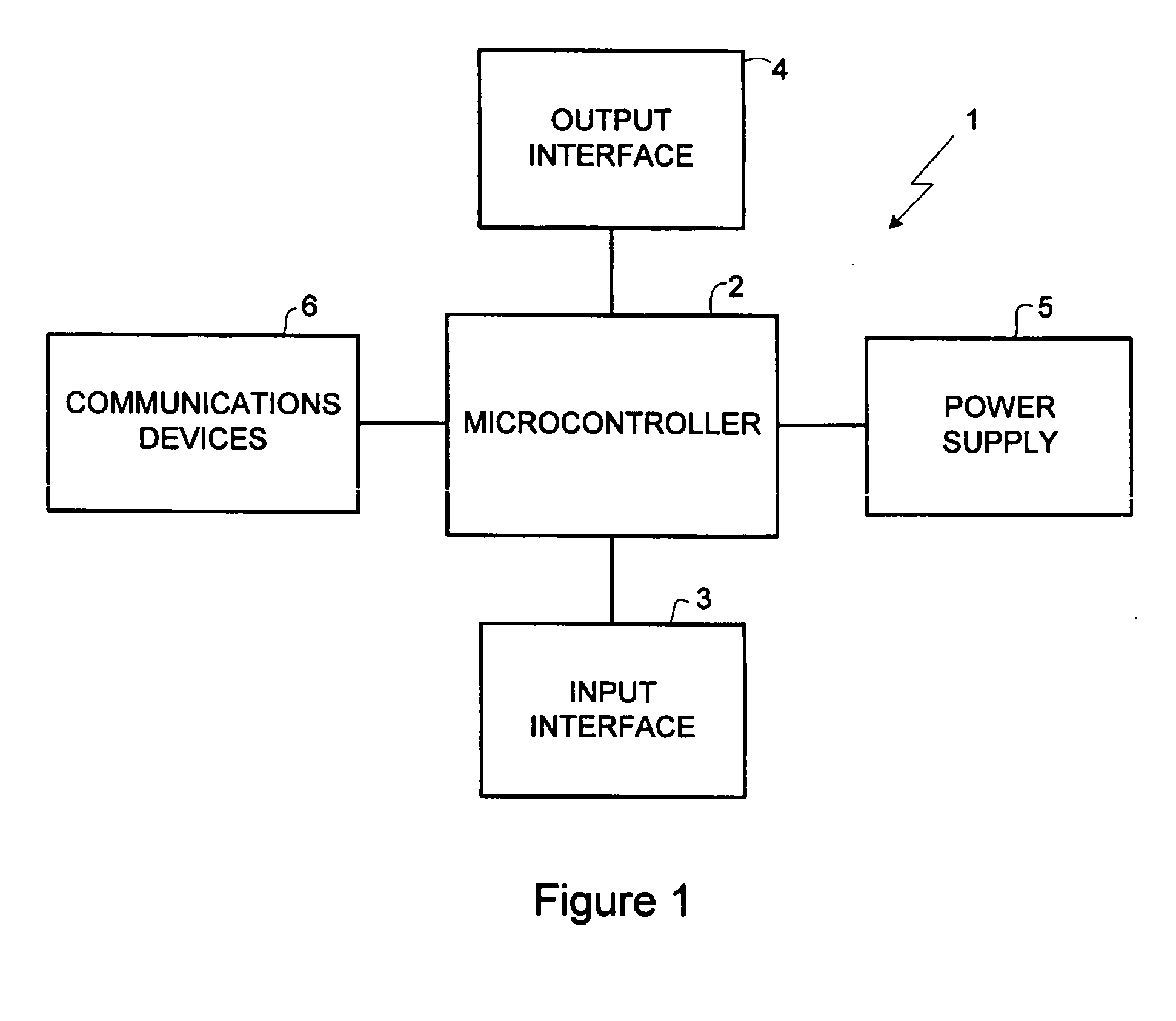
[0026] Electronic parking meters 1, as illustrated in FIG. 1, basically include a microcontroller 2, an input interface 3, an output interface 4, communications devices 6 and a power supply 5. The microcontroller 2 receives instructions through the input interface 3 from a user wishing to purchase parking time, controls the output interface 4 to provide parking related messages or indications, and controls the electronic parking meter's communications with other devices through the communications devices 6 for transmitting and receiving information and data. In addition, the electronic parking meter 1 is powered by a power supply 5, which normally uses a battery pack as a power source.

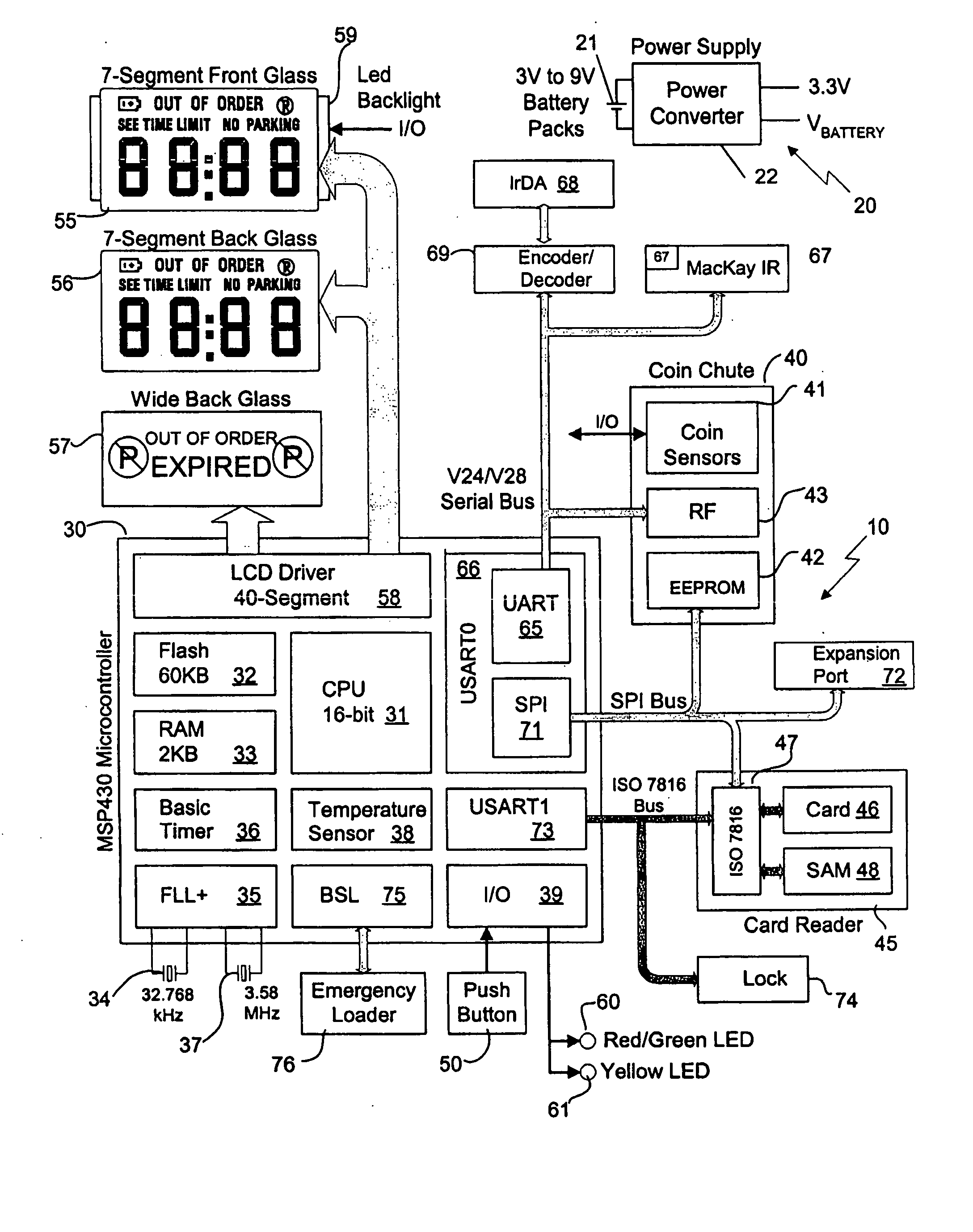
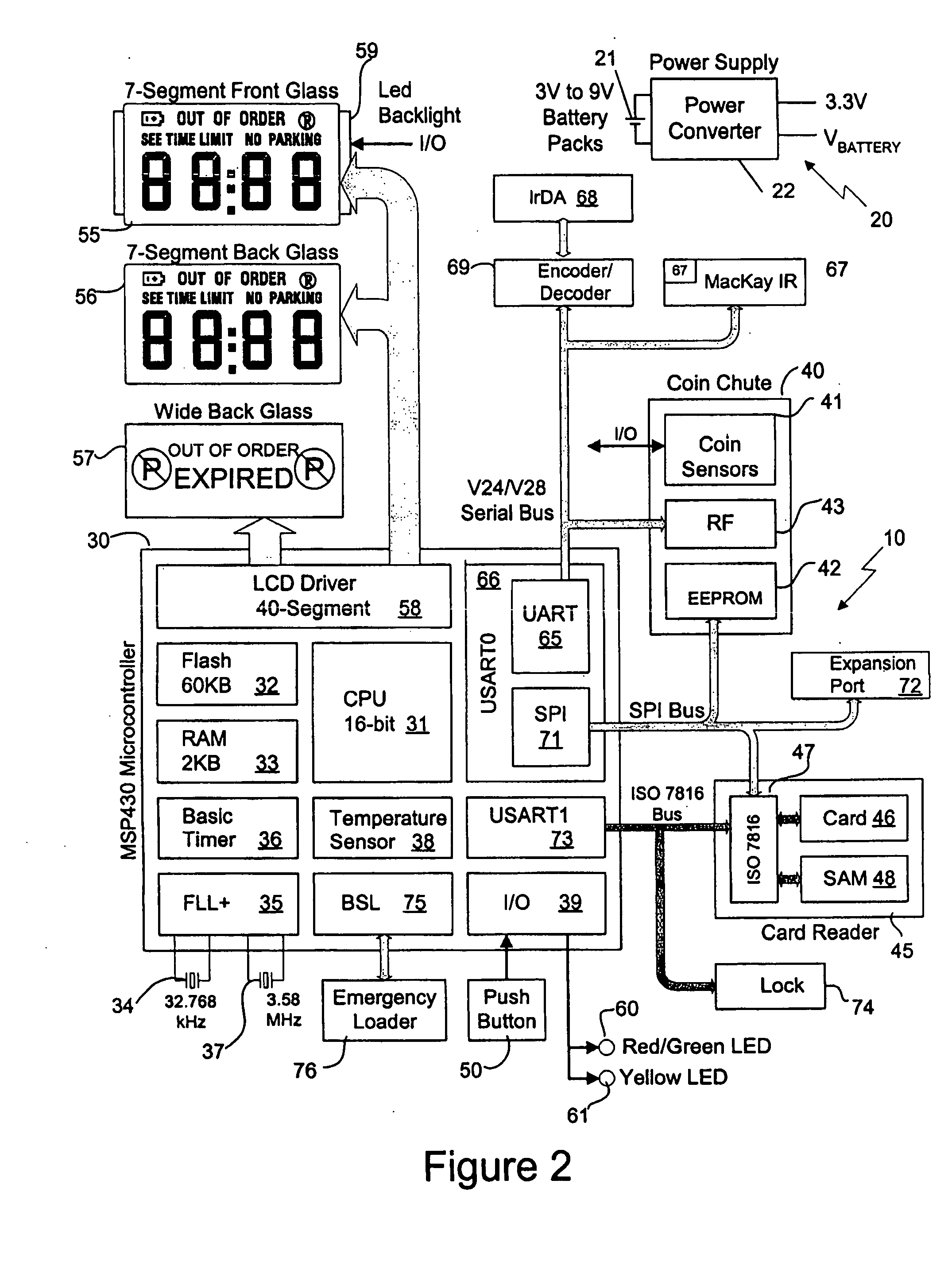
[0027]FIG. 2 illustrates an embodiment of the electronic parking meter 10 in accordance with the present invention. In the present embodiment, the components of the electronic parking meter 10 have virtually all been selected to operate from a 3.3 volt power supply 20 in order to contribute to the ene...


PUM


Abstract

The electronic parking meter includes a microcontroller, an input interface, an output interface, communications devices and a power supply. The microcontroller receives instructions through the input interface from a user wishing to purchase parking time, controls the output interface to provide parking related messages or indications, and controls the electronic parking meter's communications with other devices through the communications devices for transmitting and receiving information and data. The power supply, which converts a battery pack voltage up to the operating voltage, may include an isolation transformer and a flyback switcher. The parking meter is maintained in a sleep mode as a default state, is placed in a schedule wake-up mode at a predetermined frequency for a predetermined short period of time to carry-out maintenance functions, and is only placed in an event wake-up mode for the time required to process major events, such as coin chute, card reader or communications port interrupts. The maintenance-free life of the parking meter is extended by using more of the energy that is available in standard battery packs and by decreasing energy consumed in the parking meter to carry out its functions through the three operating modes including the periodic schedule wake-up mode.

Description

[0001] This application claims the benefit of U.S. Provisional Patent Application Ser. No. 60 / 537,039 filed on Jan. 20, 2004.FIELD OF INVENTION [0002] The present invention relates generally to single space electronic parking meters, and more particularly to an energy efficient electronic parking meter. BACKGROUND OF THE INVENTION [0003] Parking authorities continue to look to the use of single space parking meters as a source of revenue from both on street parking as well as parking in unattended parking lots. However, in addition, these parking spaces are also used to entice car drivers to certain areas of a city by allowing parking for limited periods of time thus assuring the availability of parking. Therefore parking meters must be convenient, easy to operate and very versatile in terms of the variety and clarity of the messages that they display. [0004] In order to respond to such a need, electronic parking meters have been developed. Examples of such parking meters are the Wa...

Claims


Application Information

Patent Timeline
Patent Type & Authority Applications(United States)
IPC IPC(8): G07B15/02G07D7/00
CPCG07B15/02
Inventor BANKS, KENEDSALL, ROBMACDONALD, ALLANMACKAY, GEORGE
Owner J J MACKAY CANDADA
Learn More