Cylindrical telescopic structure cyclone apparatus

a cyclone apparatus and cylindrical telescopic technology, applied in the direction of chemistry apparatus and processes, reversed direction vortex, solid separation, etc., to achieve the effect of low separation efficiency, high pressure drop and energy consumption

Inactive Publication Date: 2005-07-21
TUSZKO WLODZIMIERZ J +1
View PDF9 Cites 32 Cited by
  • Summary
  • Abstract
  • Description
  • Claims
  • Application Information

AI Technical Summary

Benefits of technology

[0007] This invention relates to a device for separating of particulate fluid suspension known as a cyclone separator, in which centrifugal forces of the revolving particulate suspension cause separation of the suspension into finer and coarser or light and denser fractions. The conventional of the conical predominating shape cyclone features of both high pressure drop and energy consumption to get a low separation efficiency for low capacity. This conical cyclone portion participates in creating so-called “back mix” and is vulnerable to be fast eroded.
[0008] To avoid those harmful phenomenons the present invention provides cylindrical-telescopic cyclone structure and multi-compartment separation chamber with air core or without it.

Problems solved by technology

A frequent problem with this and later hydrocyclone devices are—so called “back mix,” high pressure drop and fast erosion of the conical portion.

Method used


Image

  • Cylindrical telescopic structure cyclone apparatus
  • Cylindrical telescopic structure cyclone apparatus
  • Cylindrical telescopic structure cyclone apparatus

Examples


Embodiment Construction

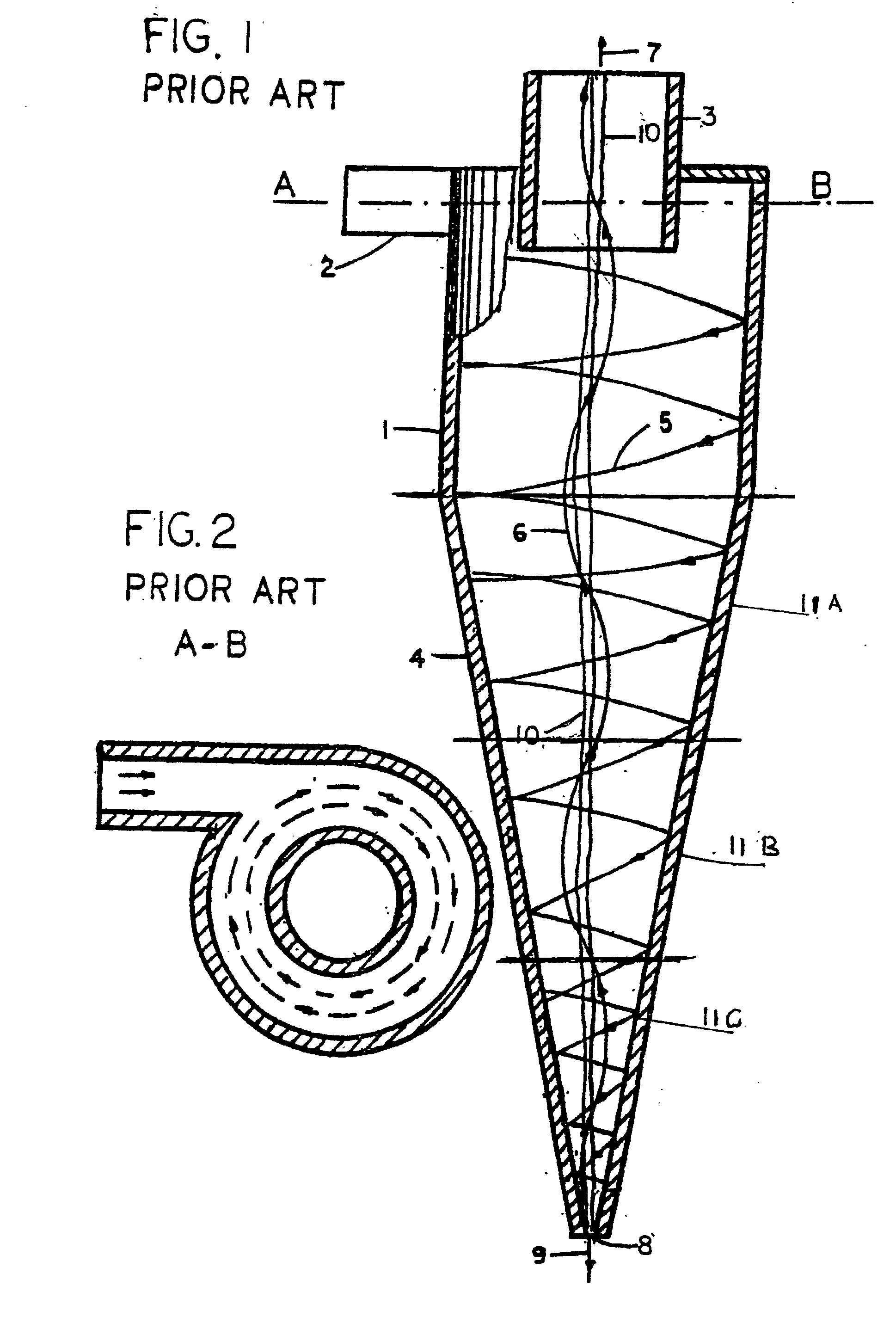
[0016] A conventional conical cyclone for separating of fluid mixtures which are centrifugally separable is illustrated in FIG. 1 and FIG. 2. This cyclone is comprised of short cylindrical portion 1 having an inlet duct 2 for introducing of a feed suspension or feed mixture in tangential direction. An exhaust or overflow pipe 3 extends through the top or ceiling wall of the cylindrical portion 1. A frustum-conical portion 4 is axially aligned with the exhaust pipe 3. In the portion 1 and 4 together as in separating chamber the feed suspension of feed mixture flows in the helical swirling flow pattern so to establish counter-flowing outer 5 and inner 6 vortexes within the separating chamber inherently causing solids in the fluid flow, which are smaller or lighter to move to the inner vortex 6 and exit through overflow pipe 3 as a smaller or lighter product stream or overflow 7. Ingredients in the fluid flow which are coarser or heavier move to the outer vortex 5 and exit through the ...


PUM


Abstract

The cylindrical-telescopic cyclone apparatus structure pattern is the base for multi-compartment cylindrical-telescopic separation chamber cyclone as well as for one compartment conical separation chamber cyclone for both to be a most economic solution.

Description

[0001] This Application is of Continuation in Part-Application to application Ser. No. 10 / 623326 dated Jul. 19, 2003, now abandoned. This invention is relates to an apparatus for continuous separation of solid-solid, solid-fluid suspension of particulate material. More specifically, the invention is directed to considerably increasing capacity and separation efficiency as well as to reduce pressure drop compared to the conventional conical cyclone separator.BACKGROUND [0002] An early hydrocyclone method and apparatus from U.S. Pat. No. 453,105 (Bretney) issued May 28, 1891 in which there were two stages, in line, in the separating hydrocyclone. A frequent problem with this and later hydrocyclone devices are—so called “back mix,” high pressure drop and fast erosion of the conical portion. [0003] A hydrocyclone is a device for creation of a free vortex, and it is the vortex that does the work in separating the particle matter from liquid. [0004] The new features of the hydrocyclone-ai...

Claims


Application Information

Patent Timeline
Patent Type & Authority Applications(United States)
IPC IPC(8): B04C5/081B04C5/14
CPCB04C5/14B04C5/081
Inventor TUSZKO, WLODZIMIERZ J.TUSZKO, WOJCIECH
Owner TUSZKO WLODZIMIERZ J
Why Eureka
Try Eureka