Door lock mechanism and door lock unit

a door lock and mechanism technology, applied in the field of door lock mechanisms, to achieve the effect of accurate operation of the door lock mechanism, convenient handling of the door lock unit, and ensuring the independence of the lock claw

Inactive Publication Date: 2005-07-21
NIFCO INC +2
View PDF22 Cites 18 Cited by
  • Summary
  • Abstract
  • Description
  • Claims
  • Application Information

AI Technical Summary

Benefits of technology

[0015] According to the present invention, the lock release operation piece may be formed of an operation lever to be displaced in the direction toward the lock released state of the lock claw as the, lock release operation. The transmission member is integrated with the operation lever. Accordingly, it is possible to perform operations such as locking with the lock claw and releasing the lock through an operation of the operation lever. It is also possible to apply a damping force to a member moving accompanying with the returning movement of the lock claw after an operation of the operation lever. Accordingly, even if the lock release operation piece is of a operation lever type, it is possible to obtain the same operating effect as described above.
[0016] According to the present invention, a rack and a rotation type damper rotating for generating a damping force while engaging with the rack may be used as the damping device. Accordingly, it is possible to obtain the same operating effect as described above and make the door lock mechanism compact through the rack and the rotation type damper.
[0017] According to the present invention, when t

Problems solved by technology

Accordingly, after a lock release operation on the lock release operation piece, when the hand is removed from the lock release operation piece, in a case that the door opens relatively slower than the lock claw returns to the locked state (the door is disposed inclined toward a closed side in the closed s

Method used


Image

  • Door lock mechanism and door lock unit
  • Door lock mechanism and door lock unit
  • Door lock mechanism and door lock unit

Examples


second embodiment

[0054] In the second embodiment shown in FIG. 8, an attachment part 58 is extended from the main body part 21, and the rotation type damper 20 engaging the rack part 57 is attached to the attachment part 58. Accordingly, it is possible to incorporate all the lock mechanisms into the lock unit 19, so that the lock unit 19 (attachment part 58) is attached to the lid 4 (inner panel 10) to form the lock mechanism 18.

third embodiment

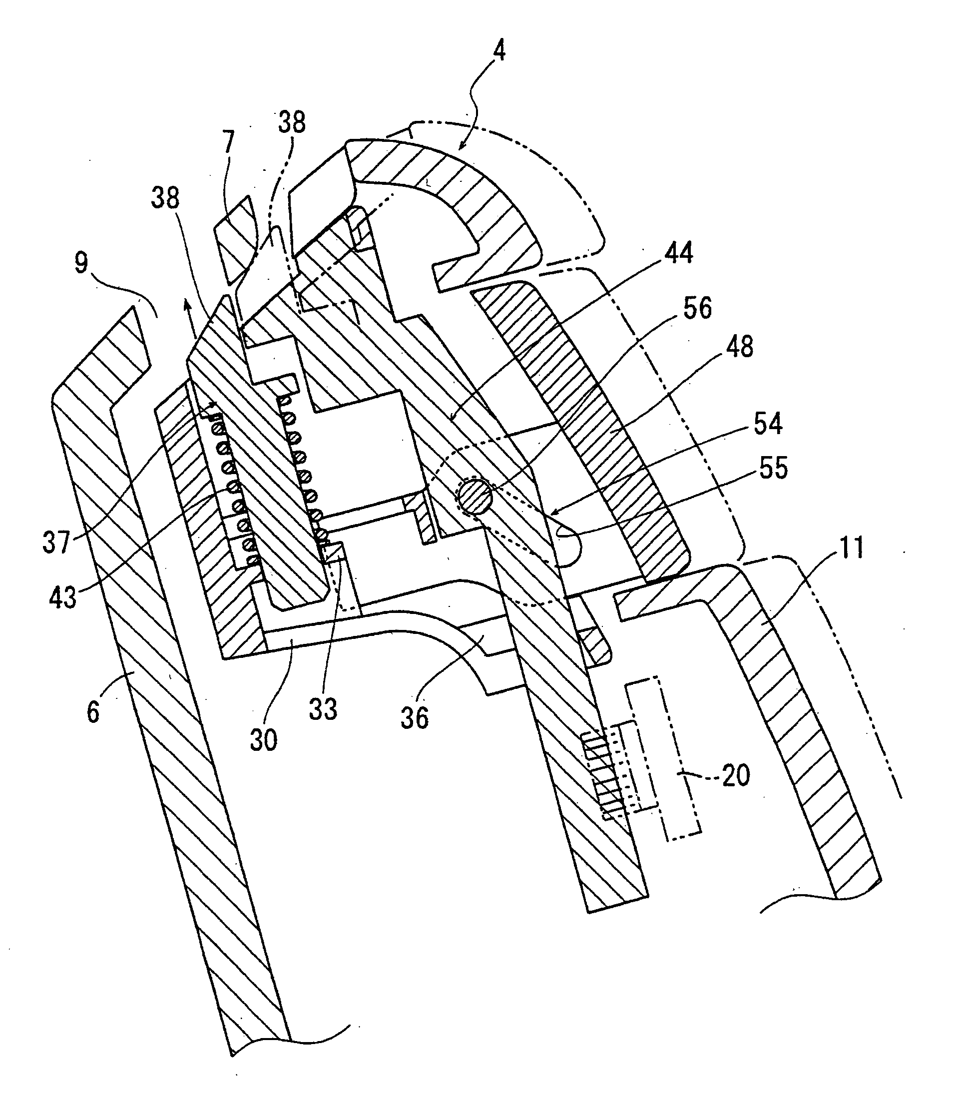
[0055] In the third embodiment shown in FIG. 9, an operation lever 59 is provided as the lock release operation piece. The operation lever 59 is integrated directly with the transmission member 44 without interposing a mechanism such as the push button switching mechanism 54. The operation lever 59 is arranged to move the lock claw 37 in the lock releasing direction. That is, when the operation lever 59 moves, a operating force is transmitted to the lock claw 37 through the transmission member 44, so that the claw part 38 of the lock claw 37 is pulled down into the main body part 21. When the operation lever 59 is released, the claw part 38 returns. At this time, the damping force is applied to the movement as in the embodiments described above. Accordingly, it is possible to assuredly prevent the claw part 38 from engaging the coupling hole 9 again, thereby making it possible to assuredly open the lid 4.

[0056] The embodiments have been explained above, and may have the following fe...


PUM


Abstract

A door lock mechanism includes a lock claw, a spring attached to the lock claw for urging the same in a direction toward a lock state, a lock release operation piece linked to the lock claw for moving the lock claw in a direction toward a lock release state against a force of the spring when a lock release operation is performed, and a damping device for applying a damping force to the lock claw when the lock release operation is canceled. The lock release operation piece returns the lock claw to the lock state with the force when the lock release operation is canceled. The lock release operation piece is arranged to be separated from the lock claw when the lock claw returns from the lock release state to the lock state with an external force applied to the lock claw.

Description

BACKGROUND OF THE INVENTION AND RELATED ART STATEMENT [0001] The present invention relates to a door lock mechanism for locking a door and a door lock unit including the door lock mechanism. [0002] Various members in an automobile including an instrument panel are provided with a housing mechanism as a compartment and the like. As disclosed in Patent Document 1, such a housing mechanism has a box with an opening and a door attached to the box for opening and closing the opening (generally in an urged state with a spring in an open direction). A lock mechanism is provided on the door for maintaining a closed state of the door when the door closes the opening. The lock mechanism has, for example, a lock claw always urged in a direction toward a locked state, and a lock release operation piece for releasing the lock claw to a lock released state. When the opening is closed by the door, the lock claw engages a coupling part on the box. When the lock release operation piece is released, ...

Claims


Application Information

Patent Timeline
IPC IPC(8): E05C1/14B60R7/06E05B17/00E05B83/30E05B85/22E05C21/00
CPCE05B83/30E05B77/42Y10S292/37E05C1/145Y10T292/0926Y10T292/0969Y10T292/0972Y10T292/0976Y10T292/0993E05B17/0041E05B63/127
Inventor NEMOTO, TAKEHIKOMAEDA, TORUKAERIYAMA, HIDEHARUKONDOU, HIRONOBU
Owner NIFCO INC
Why Eureka
Try Eureka