Bumper beam structure

a beam structure and bumper technology, applied in bumpers, vehicle components, vehicular safety arrangments, etc., can solve the problems of increased machine cost, increased equipment cost, and ineffective transmission of impact force applied obliquely from the front to the vehicle frame, so as to facilitate the provision of desirable strength, facilitate the adjustment of the strength of the supporting portion, and the effect of molded relatively easily

Inactive Publication Date: 2005-07-21
HONDA MOTOR CO LTD
View PDF2 Cites 19 Cited by
  • Summary
  • Abstract
  • Description
  • Claims
  • Application Information

AI Technical Summary

Benefits of technology

[0022] Thus, the right and left ends of the beam are supported by the supporting portions of the right and left corner members, and the supporting portions are reinforced by the walls. The thickness of the walls can be adjusted to easily adjust the strength of the supporting portions, which facilitates provision of a desirable strength required by the bumper beam.
[0023] The beam and the right and left corner members are preferably made from aluminum material. Aluminum material is molded relatively easily, and is a suitable material for extrusion molding. The beam and the corner members are made from aluminum material to increase productivity of the bumper beam. Aluminum material is a light material, resulting in a reduced weight of the bumper beam.
[0024] According to the embodiment of the present invention, the right and left corner members are preferably connectable to the vehicle frame members via respective mounting brackets made from extruded aluminum material. According...

Problems solved by technology

The integration of the rolling mill and the extruding machine leads to large equipment, increasing the cost of equipment.
Accordingly, it is necessary to increase the machining accuracy of the rolling mill for rolling the beam 101 and ...

Method used


Image

  • Bumper beam structure
  • Bumper beam structure
  • Bumper beam structure

Examples


Embodiment Construction

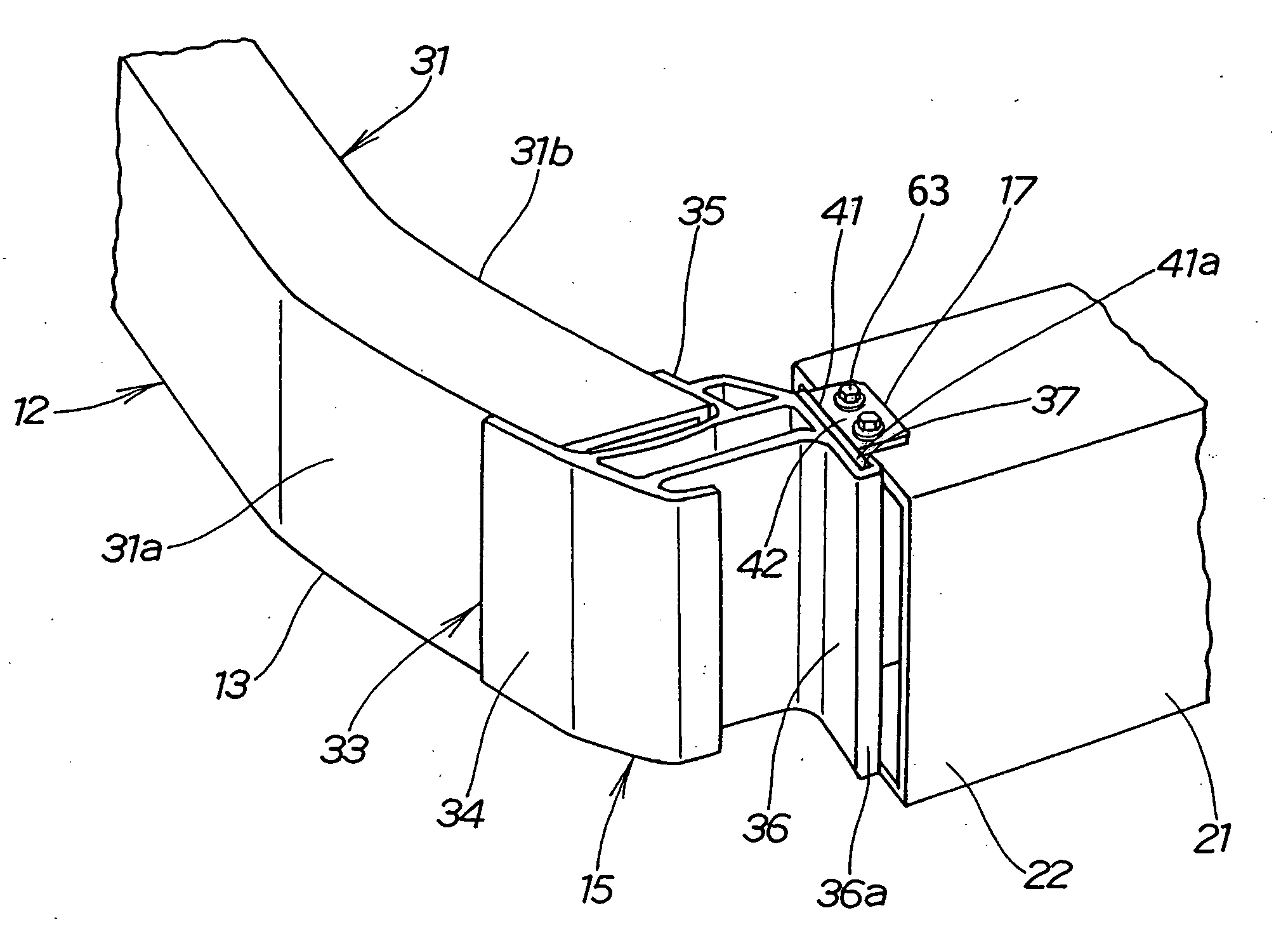
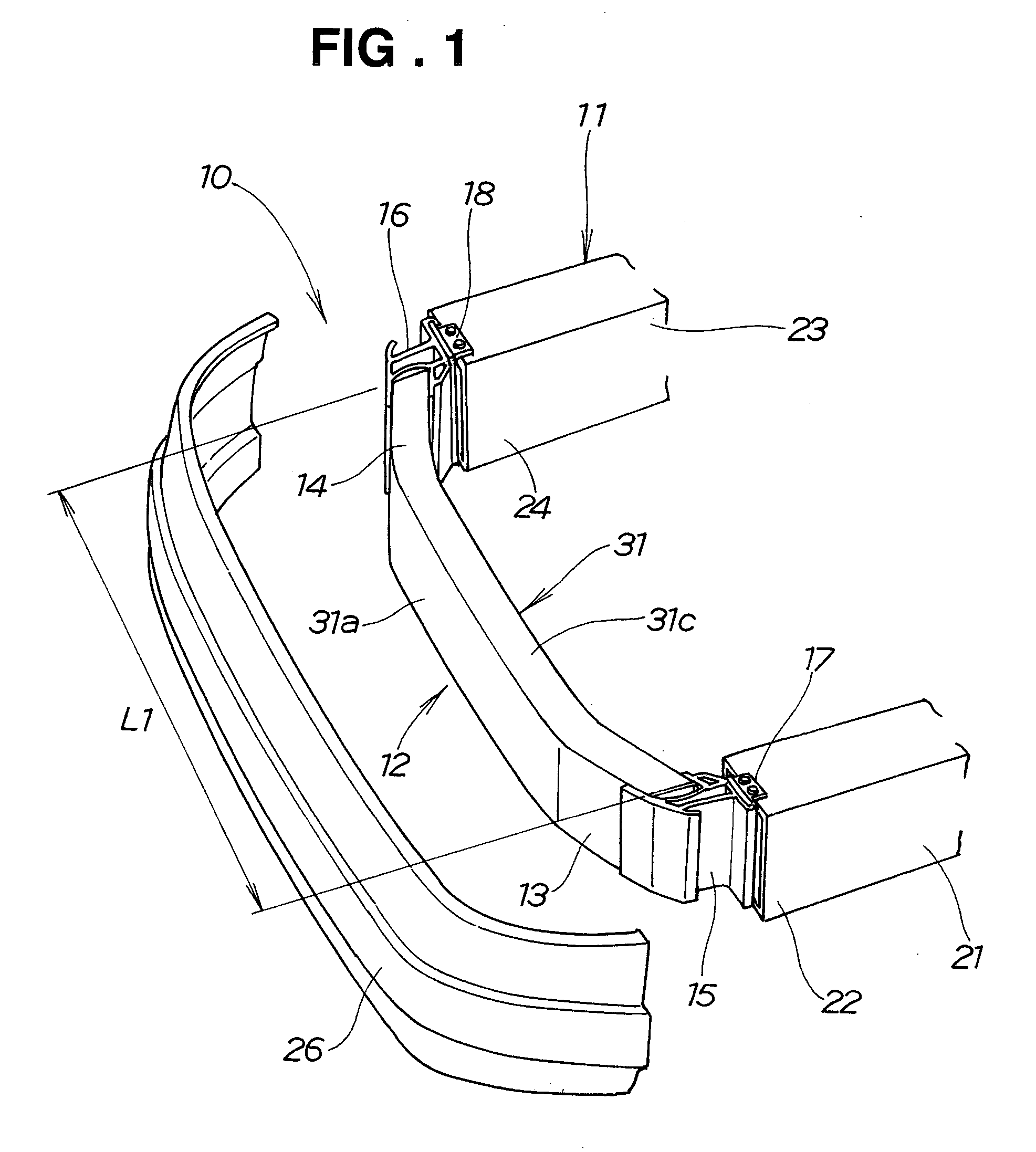
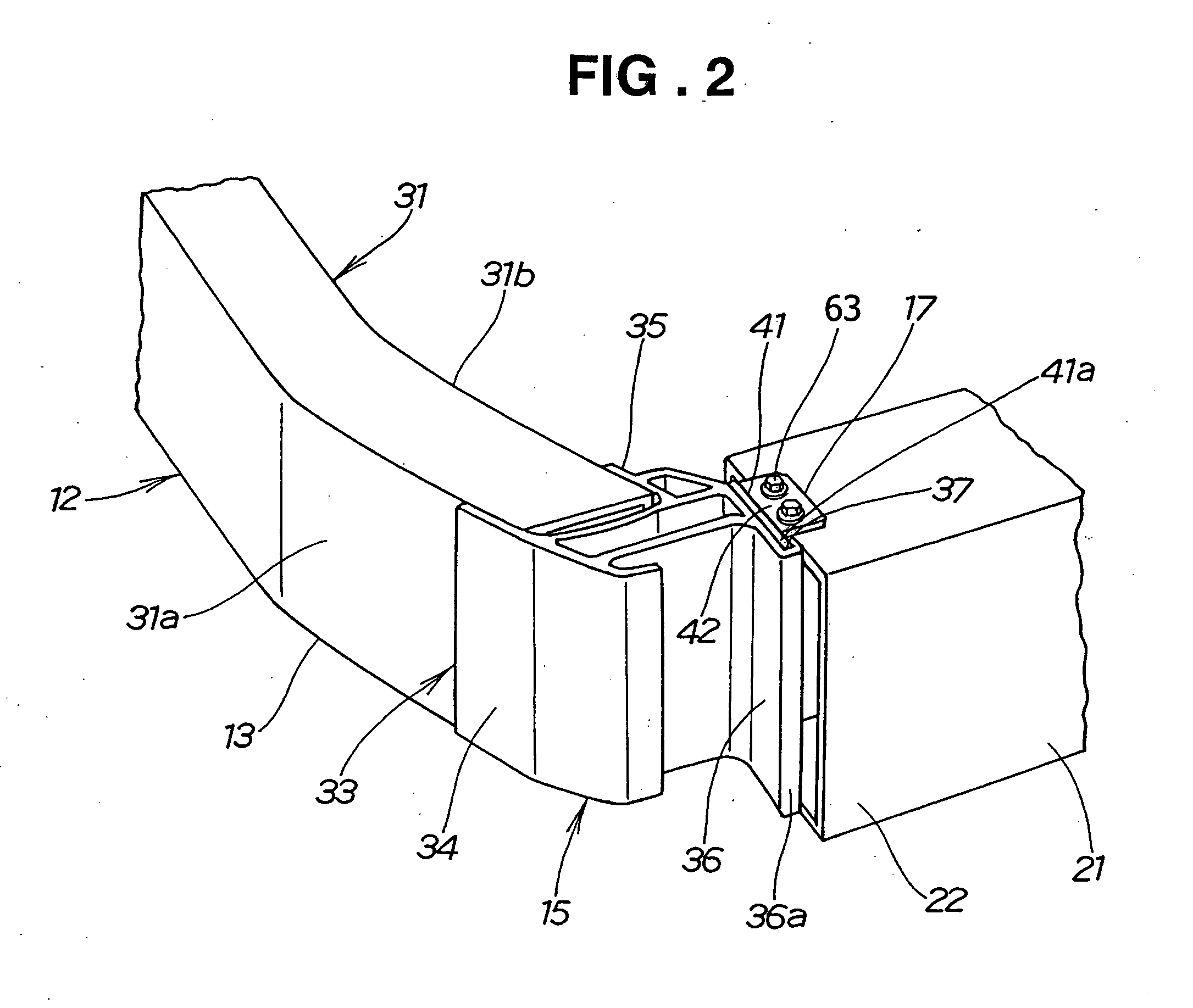
[0034] A bumper beam structure 10 according to the present invention shown in FIG. 1 includes a beam 12 disposed at the front of a vehicle body 11 (body end) in a transversely extending manner, and left and right corner members 15, 16 attached to left and right ends 13, 14 of the beam 12. The left corner member 15 is mounted to a front end 22 of a left front side member (vehicle frame member) 21 via a left mounting bracket 17. The right corner member 16 is mounted to a front end 24 of a right front side member (vehicle frame member) 23 via a right mounting bracket (mounting bracket) 18.

[0035] That is, the bumper beam structure 10 has the beam 12 mounted to the left and right front side members 21, 23 via the left and right corner members 15, 16 and the left and right mounting brackets 17, 18.

[0036] A bumper cover 26 is attached to the front of the beam 12 and the left and right corner members 15, 16.

[0037] The beam 12 is a member in a generally curved shape with its left and righ...


PUM


Abstract

A bumper beam structure includes a beam extending transversely of a vehicle and right and left corned members attached to right and left ends of the beam. The beam is mountable to front ends of right and left vehicle frame members via the right and left corner members. The beam and the right and left corner members are all extruded members. The beam is disposed with its axis in an extrusion direction oriented transversely of the vehicle. The right and left corner members are disposed with their axes in an extrusion direction oriented vertically of the vehicle.

Description

FIELD OF THE INVENTION [0001] The present invention relates to bumper beam structures, and more particularly, to bumper beam structures in which right and left corner members are attached to right and left ends of a beam, and the beam is mounted to a vehicle frame via the corner members. BACKGROUND OF THE INVENTION [0002] A bumper structure consisting of a beam extending transversely of a vehicle at the vehicle front, right and left mounting members attached to right and left ends of the beam, respectively, and right and left frame members mounted with the right and left mounting members, respectively, is disclosed in Japanese Patent Laid-Open Publication No. 2001-88633, for example. This bumper structure will be described below with reference to FIG. 7. [0003] A bumper structure 100 includes an M-shaped cross-section beam 101 extending transversely of an automobile, and left and right polymeric corner members 104, 105 constituted by extruded members, fitted to left and right ends 1...

Claims


Application Information

Patent Timeline
IPC IPC(8): B60R19/03B60R19/18B60R19/24
CPCB60R2019/182B60R19/24
Inventor SUZUKI, TOSHIHIKOITAI, YOSHIHARUOMURA, KAZUO
Owner HONDA MOTOR CO LTD
Why Eureka
Try Eureka