Signal-processing system, signal-processing method, and signal-processing program

a signal processing and signal processing technology, applied in the field of signal processing systems and signal processing methods, can solve the problems of not realizing satisfactorily efficient edge enhancement, blurring even portions that are originally edges by smoothing, and enhancing noise components. , to achieve the effect of performing edge enhancement appropriately and efficiently

Inactive Publication Date: 2005-07-21
OLYMPUS CORP
View PDF8 Cites 39 Cited by
  • Summary
  • Abstract
  • Description
  • Claims
  • Application Information

AI Technical Summary

Benefits of technology

[0012] It is an object of the present invention to provide a signal-processing system, a signal-processing method, and a signal-processing program that are capable of performing edge enhancement appropriately and efficiently.

Problems solved by technology

In most cases, however, image signals include noise components, and therefore, the edge enhancement using differentiation, as mentioned above, has a problem in that these noise components are also enhanced.
However, the use of the means in which smoothing is carried out before edge extraction, as disclosed in Japanese Unexamined Patent Application Publication No. 58-222383, blurs even portions that are originally edges by smoothing.
Therefore, satisfactorily efficient edge enhancement is not realized.
The means dividing into areas according to brightness, as described in Japanese Unexamined Patent Application Publication No. 9-270005, performs insufficient edge enhancement in accordance with a subject since the means cannot identify the subject in terms of a characteristic color, such as the color of human skin, that of the sky, or that of a plant.

Method used


Image

  • Signal-processing system, signal-processing method, and signal-processing program
  • Signal-processing system, signal-processing method, and signal-processing program
  • Signal-processing system, signal-processing method, and signal-processing program

Examples


first embodiment

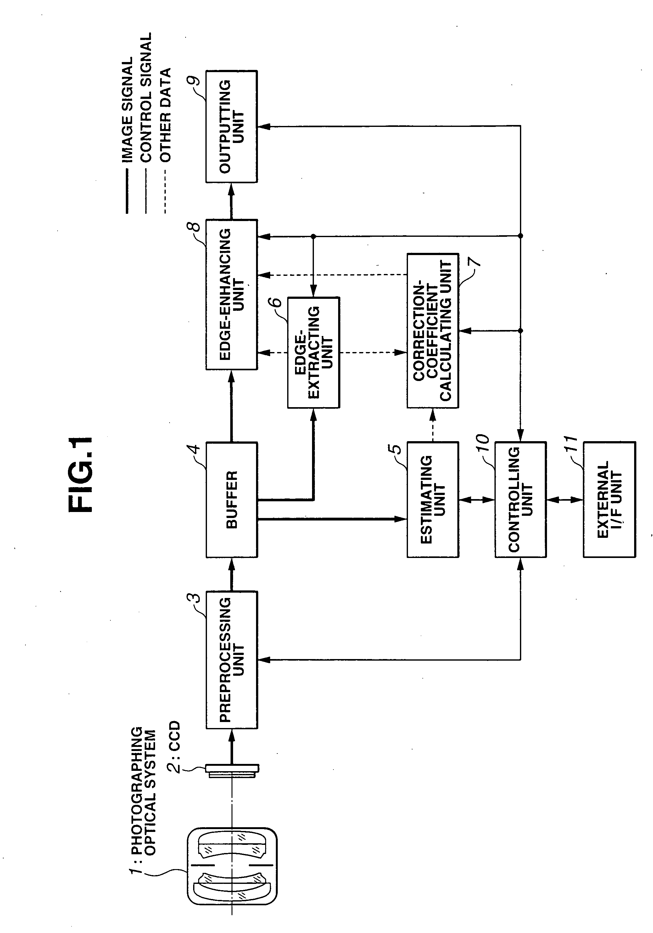
[0033] FIGS. 1 to 10 illustrate a first embodiment of the present invention. FIG. 1 is a block diagram showing the structure of a signal-processing system.

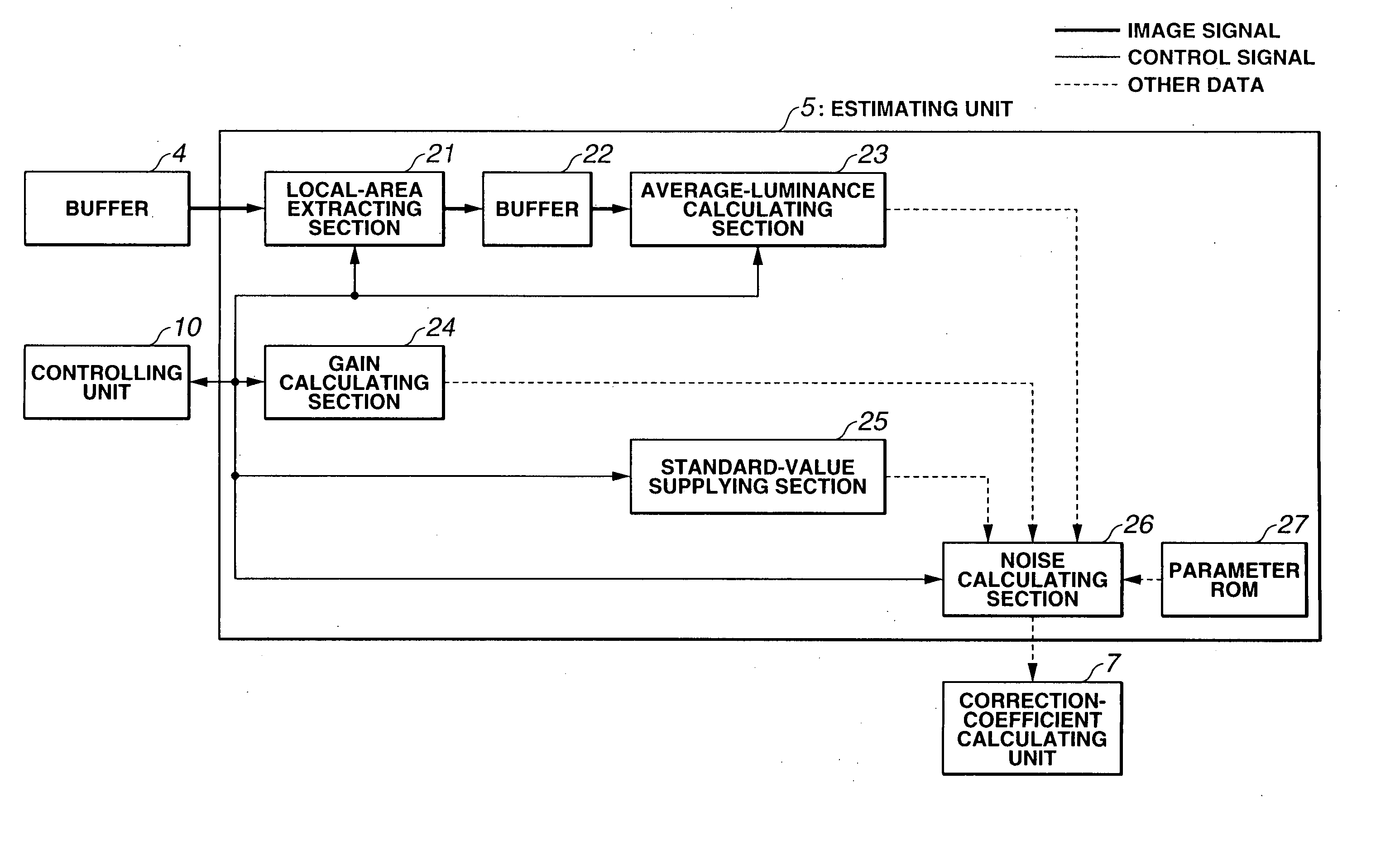
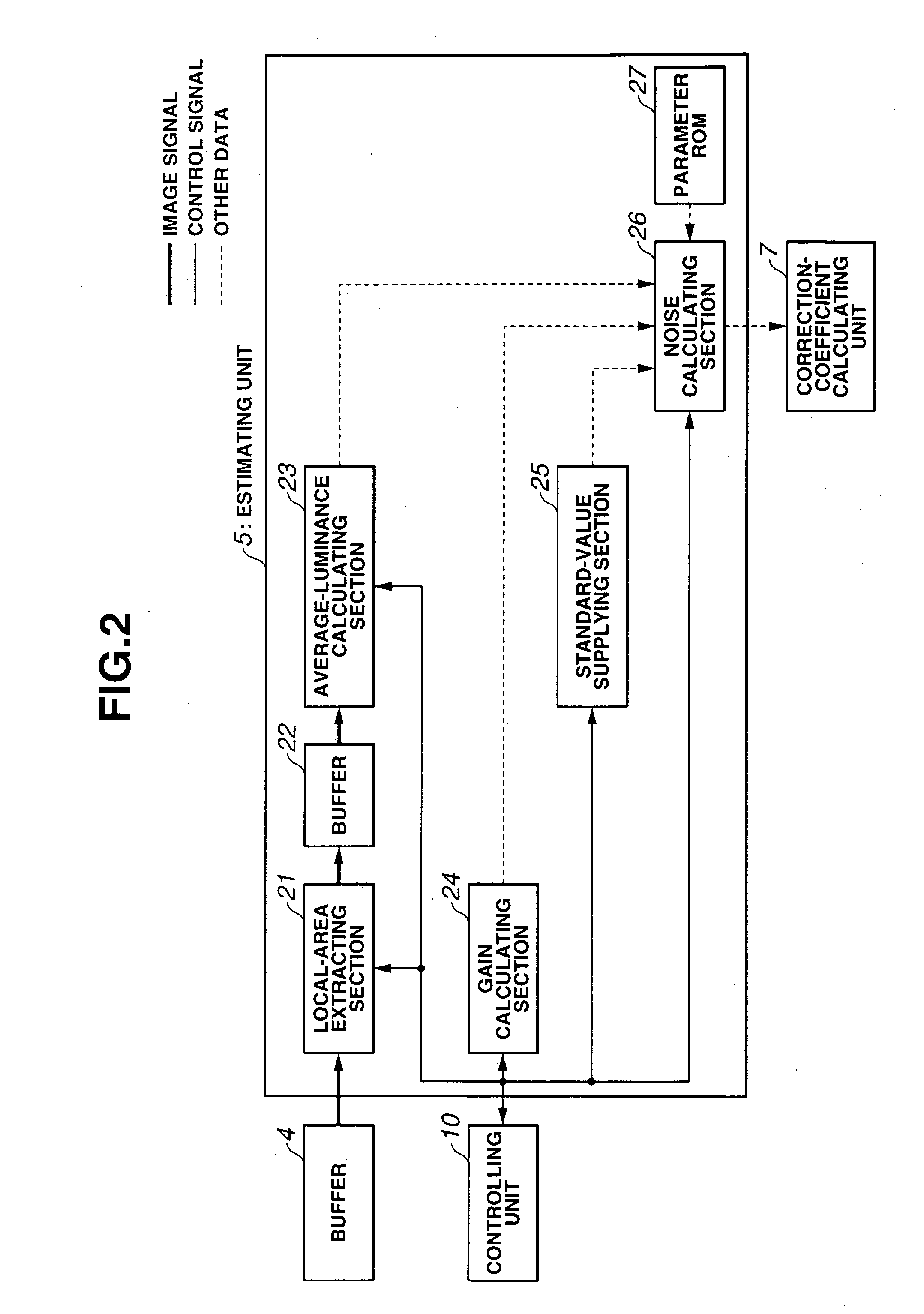
[0034] Referring to FIG. 1, this signal-processing system includes a photographing optical system 1 for forming a subject image; a charge-coupled device (CCD) 2 constituting an image-capturing device for photoelectrically converting the optical subject image formed by the photographing optical system 1 to output an electrical image signal; a preprocessing unit 3 for amplifying a gain of the analog image signal output from the CCD 2 and analog-to-digital converting the image signal into digital form and for performing processing, such as autofocus (AF) control or auto-exposure (AE) control; a buffer 4 for temporarily storing the digital image signal output from the preprocessing unit 3; an estimating unit 5 serving as estimating means for performing processing, such as noise estimation or scene estimation, which are described late...

second embodiment

[0138]FIGS. 11 and 12 illustrate a second embodiment of the present invention. FIG. 11 is a block diagram showing the structure of the signal-processing system. FIG. 12 is a block diagram showing an example of the structure of the edge-extracting unit.

[0139] In this second embodiment, the same reference numerals are used as in the first embodiment for similar parts and the explanation thereof is omitted; the differences will be mainly described.

[0140] As shown in FIG. 11, the signal-processing system of the second embodiment is the same as that shown in FIG. 1, except that an edge-controlling unit 12 serving as edge-controlling means is added.

[0141] The edge-controlling unit 12 is used for controlling operations of the edge-extracting unit 6 and the edge-enhancing unit 8 under the control of the controlling unit 10 and is interactively connected to the edge-extracting unit 6, the edge-enhancing unit 8, and the controlling unit 10.

[0142] The flow of signals in the signal-processi...

third embodiment

[0154] FIGS. 13 to 15 illustrate a third embodiment of the present invention. FIG. 13 is a block diagram showing the structure of the signal-processing system. FIG. 14 is a block diagram showing an example of the structure of an image-dividing unit. FIG. 15 is a flowchart showing an example of software signal processing based on a signal-processing program.

[0155] In this third embodiment, the same reference numerals are used as in the first and second embodiments for similar parts and the explanation thereof is omitted; the differences will be mainly described.

[0156] This signal-processing system is the same as that shown in FIG. 1, except that, in place of the estimating unit 5, an image-dividing unit 13 serving as image-dividing means is provided.

[0157] The image-dividing unit 13 divides an image signal stored in the buffer 4 into areas, each having a predetermined size, labels the areas, and transfers their results to the correction-coefficient calculating unit 7. The image-di...


PUM


Abstract

In a signal-processing system, an image signal image captured by a CCD is converted into digital form by a preprocessing unit. An estimating unit estimates the amount of noise or a scene from the image signal as a characteristic amount. An edge-extracting unit extracts an edge component in an image associated with the image signal. A correction-coefficient calculating unit calculates a correction coefficient for correcting the edge component in accordance with the characteristic amount and the edge component. An edge-enhancing unit performs edge enhancement with respect to the image signal on the basis of the edge component and the correction coefficient.

Description

[0001] This application claims benefit of Japanese Application No. 2003-365185 filed in Japan on Oct. 24, 2003, the contents of which are incorporated by this reference. BACKGROUND OF THE INVENTION [0002] 1. Field of the Invention [0003] The present invention relates to a signal-processing system, a signal-processing method, and a signal-processing program for processing image signals in digital form. [0004] 2. Description of the Related Art [0005] Hitherto, edge enhancement for sharpening edges of images has been used. One such edge enhancement employs, for example, means for differentiating supplied image signals. [0006] In most cases, however, image signals include noise components, and therefore, the edge enhancement using differentiation, as mentioned above, has a problem in that these noise components are also enhanced. [0007] A technology to address such a problem is disclosed in, for example, Japanese Unexamined Patent Application Publication No. 58-222383, in which smoothin...

Claims


Application Information

Patent Timeline
Patent Type & Authority Applications(United States)
IPC IPC(8): G06T5/20G06T5/00H04N1/409H04N1/60H04N5/208H04N5/228H04N5/232H04N5/235
CPCH04N1/4092H04N1/6072G06T2207/20192G06T5/003H04N5/208
Inventor SAMBONGI, MASAO
Owner OLYMPUS CORP
Why Eureka
Try Eureka