Apparatus and method for displaying image

a liquid crystal projector and apparatus technology, applied in the direction of picture reproducers using projection devices, color television details, instruments, etc., can solve the problems of inability to change the locus of the resultant electric field vector of incident light, the brightness of the image may become non-uniform, and the uniformity may deteriorate, so as to improve the black-level display and achieve the effect of higher contrast imag

Inactive Publication Date: 2005-07-21
SONY CORP
View PDF10 Cites 5 Cited by
  • Summary
  • Abstract
  • Description
  • Claims
  • Application Information

AI Technical Summary

Benefits of technology

[0034] The invention is designed to overcome the foregoing problems. It is an object of the invention to provide a projection type liquid crystal display apparatus, which can improve black-level display and thus can display a higher-contrast image as compared to the related art.
[0035] It is another object of the invention to prevent deterioration in contrast and uniformity due to properties of dependence on viewing angles through an approach suitable for a liquid crystal projector apparatus using a TN liquid crystal panel or an STN liquid crystal panel (in particular, a transmission type liquid crystal projector apparatus having liquid crystal panels each having microlenses for increasing a numerical aperture, as illustrated in FIGS. 1 and 2).

Problems solved by technology

As a result, it becomes impossible to change the locus of a resultant electric field vector of the incident light according to initial level.
In the case where the cell gap lengths vary according to parts of the liquid crystal panel, even when an image of the same brightness over the overall screen should be displayed (voltages on the same level are applied to all pixels), the properties of dependence on viewing angles cause variations in the transmittance of light passing through an analyzer after entering obliquely into the liquid crystal panel and then exiting from the liquid crystal panel, according to the parts of the liquid crystal panel, and therefore the brightness of the image may become nonuniform (that is, the uniformity may deteriorate).
As described above, an image display apparatus using a liquid crystal panel may deteriorate in contrast and uniformity due to the properties of dependence on viewing angles resulting from the existence of the pretilt angles.
Although a direct-vision type liquid crystal display is designed in consideration of the properties of dependence on viewing angles, a liquid crystal projector apparatus that is a projection type liquid crystal display is not so devised as to improve the contrast and uniformity in consideration of the properties of dependence on viewing angles.
Therefore, the deterioration in contrast and uniformity cannot be prevented even if a conventional approach for designing the direct-vision type liquid crystal display in consideration of the properties of dependence on viewing angles is adopted for the liquid crystal projector apparatus as it is.

Method used


Image

  • Apparatus and method for displaying image
  • Apparatus and method for displaying image
  • Apparatus and method for displaying image

Examples


first embodiment

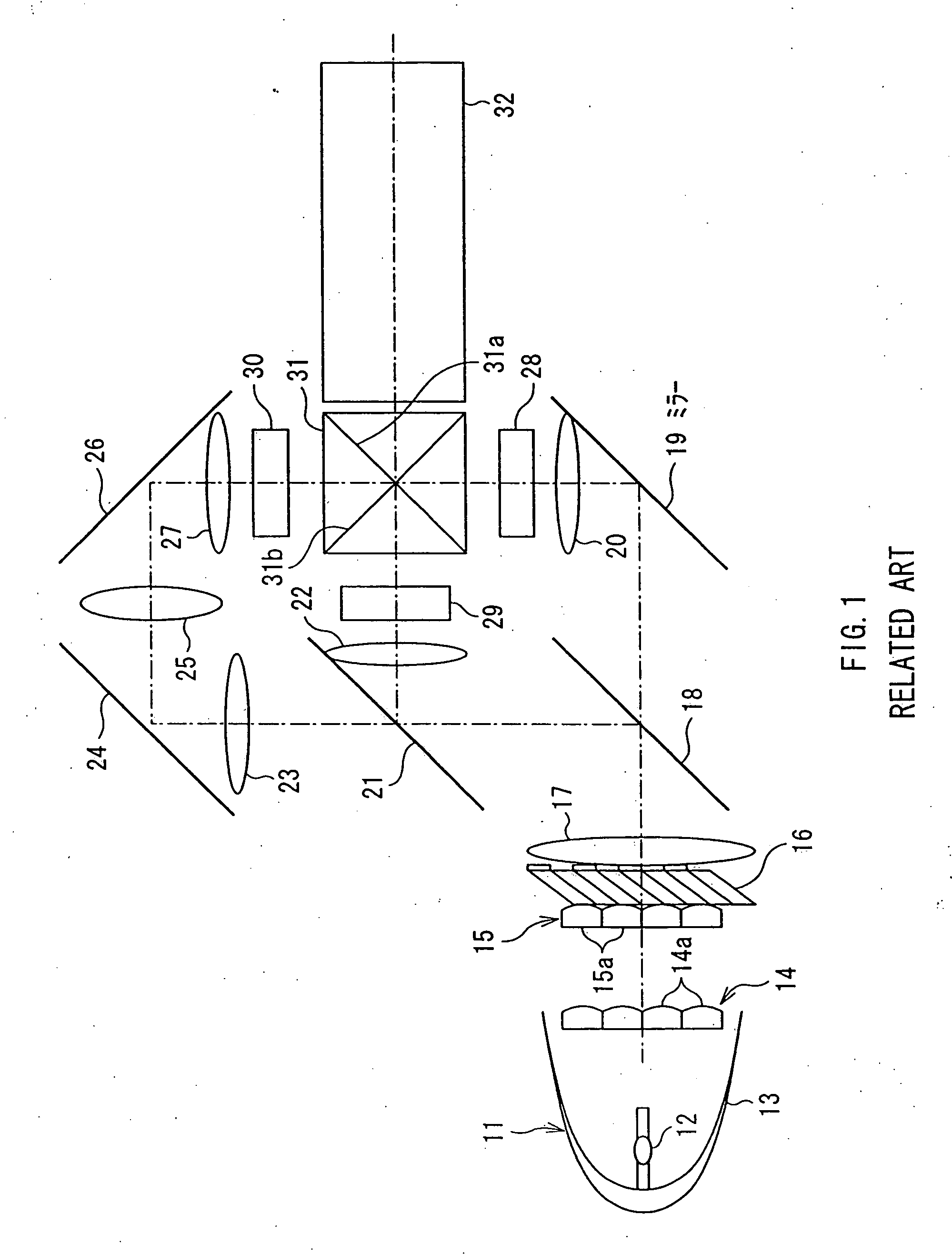
[0095] A first embodiment of the invention will be described below with reference to the drawings. FIG. 6 shows an example of a configuration of an optical system of a three-panel transmission type liquid crystal projector apparatus to which the invention is applied. Parts of the optical system, except for liquid crystal modules 1, 2 and 3, have common configurations with those of an optical system of a three-panel transmission type liquid crystal projector apparatus shown in FIG. 1, and thus the parts are indicated by the same reference numerals as the reference numerals in FIG. 1.

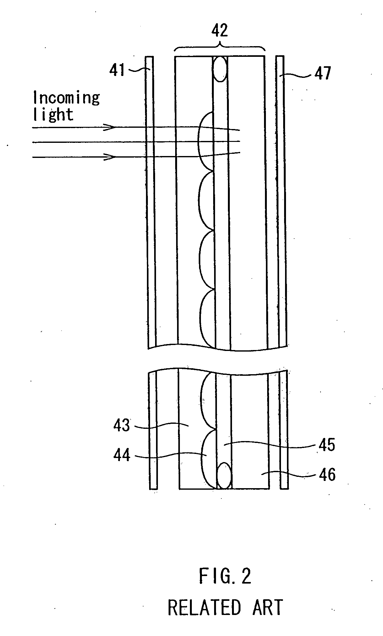
[0096] The liquid crystal modules 1, 2 and 3 have the same configuration. FIG. 7 shows an example of a configuration of an optical system of each of the liquid crystal modules 1, 2 and 3, and parts having common configurations with parts shown in FIG. 2 are indicated by the same reference numerals as the reference numerals in FIG. 2. The invention is characterized by that, in each of the liquid crystal m...

second embodiment

[0175] The second and third embodiments of the invention will be described in detail below with reference to the drawings. In the second and third embodiments, since a nematic liquid crystal molecule generally has birefringence equivalent to birefringence of a positive crystal, a phase difference caused by the birefringence of the nematic liquid crystal molecule is compensated for by using a substance having properties optically opposite to the positive crystal, namely, a substance having birefringence equivalent to birefringence of a negative crystal.

[0176]FIG. 20 shows the overall configuration of a projection type liquid crystal display apparatus according to the second embodiment of the invention. The projection type liquid crystal display apparatus shown in FIG. 20 is a three-panel type for performing color image display using three transmission type liquid crystal panels. The projection type liquid crystal display apparatus comprises a light source 211, a UV (ultraviolet) / IR ...

third embodiment

[0216] Next, the third embodiment of the invention will be described. In the following description, the same parts as the structural elements of the second embodiment are indicated by the same reference numerals, and the description thereof is appropriately omitted.

[0217]FIG. 30 shows a configuration of a principal part of each of liquid crystal panel portions of a projection type liquid crystal display apparatus according to the third embodiment of the invention. The configuration of the projection type liquid crystal display apparatus of the third embodiment is the same as the configuration of the above-described second embodiment, except for the configuration of the liquid crystal panel portion shown in FIG. 30. Also in the third embodiment, the configurations of the liquid crystal panel portions for three colors will be collectively described below because the liquid crystal panel portions for three colors have substantially the same function and configuration. A liquid crystal...


PUM

PropertyMeasurementUnit
diameteraaaaaaaaaa
incident angleaaaaaaaaaa

Abstract

Provided is a projection type liquid crystal display apparatus, which can improve black-level display and thus can display a higher-contrast image as compared to the related art. An optical compensator is located on the light exit side with respect to the liquid crystal display device so as to compensate for the optical phase difference caused by liquid crystal molecules in a light-entry-side region of the liquid crystal layer. As the optical compensator is located on the light exit side with respect to the liquid crystal display device, birefringence, caused by the liquid crystal molecules present in the light-entry-side region, is compensated for without being influenced by a microlenses provided in the liquid crystal plane. Consequently, the apparatus can improve the black-level display and thus can display a higher-contrast image as compared to the related art. Further, a phase difference caused by the birefringence of the nematic liquid crystal molecule is compensated for by using a substance having properties optically opposite to the positive crystal, namely, a substance having birefringence equivalent to birefringence of a negative crystal.

Description

BACKGROUND OF THE INVENTION [0001] 1. Field of the Invention [0002] The invention relates to a liquid crystal projector apparatus and more particularly to a liquid crystal projector apparatus adapted to prevent deterioration in contrast and uniformity due to properties of dependence on viewing angles. [0003] 2. Description of the Related Art [0004] A projector apparatus for projecting an image on a screen under magnification and thus implementing a large screen is in widespread use as an image display apparatus for indoor and outdoor use. The projector apparatus is broadly divided into a projector apparatus (a CRT projector apparatus) for projecting exiting light from a fluorescent screen of a CRT onto a screen and a projector apparatus for projecting modulated light onto a screen after modulating light emitted from a light source by means of a spatial light modulator, and, in the case of the latter, a projector apparatus (a liquid crystal projector apparatus) using a liquid crystal...

Claims


Application Information

Patent Timeline
Patent Type & Authority Applications(United States)
IPC IPC(8): G02F1/1335G02F1/13363H04N9/31
CPCG02F1/133526G02F1/13363H04N9/3197G02F2001/133567H04N9/3105G02F1/133632G02F1/133567
Inventor SUZUKI, YOSHIOMIYASAKA, SOUSHIROCHI, YOSHIKITANIMOTO, TAKESHI
Owner SONY CORP
Why Eureka
Try Eureka