Abnormality determining method, abnormality determining apparatus, and image forming apparatus

Inactive Publication Date: 2005-07-21
RICOH KK
View PDF0 Cites 79 Cited by
  • Summary
  • Abstract
  • Description
  • Claims
  • Application Information

AI Technical Summary

Benefits of technology

[0020] The present invention has been designed in consideration of the background described above, and it is a first object thereof to provide an abnormality determining method which is capable of specifying the type of an occurring abnormality to a certain extent

Problems solved by technology

When a fault occurs, all or a part of the functions of the device must be halted from the occurrence of the fault to the completion of repairs, causing a great time loss for the user.
However, if the presence of the cause of each abnormality is monitored and detected individually, the control required for this monitoring becomes extremely complicated, and as the number of types of abnormality to be detected increases, the control becomes ever more complicated.
However, since this image forming apparatus detects the occurrence of various abnormalities comprehensively by perceiving the degree to which the apparatus has deviated from a normal state, it is difficult to specify the type of the abnormality.
As a result, the maintenance response following the detection of the abnormality becomes complicated.
If a serviceperson is dispatched nevertheless due to the prediction of the occurrence of the fault, the resulting wasted labor would lead to an increase in service costs.
This manner of dispatch also leads to an increase in service costs.
Hence as the number of types of abnormality to be diagnosed increases, the calculation amount required for the diagnosis increases, making control more complicated.
According to the abnormality determining apparatus constituted in this manner, when at least one of the various abnormalities occurs, the general abnormality is determined comprehensively as “abnormality present”, and thus increasingly complicated control due to an increase in the number of types of abnormality in the determination-subject can be suppressed.
However, when the general abnormality is determined as “present” using a method of perceiving the degree of deviation from a normal state, as with the Mahalanobis distance, rather than perceiving the p

Method used


Image

  • Abnormality determining method, abnormality determining apparatus, and image forming apparatus
  • Abnormality determining method, abnormality determining apparatus, and image forming apparatus
  • Abnormality determining method, abnormality determining apparatus, and image forming apparatus

Examples


first embodiment

[0090] The first embodiment mainly serves to achieve the aforementioned first object of the present invention.

[0091] First, before describing an abnormality determining apparatus to which the first embodiment is applied, an example of an image forming apparatus serving as the detection subject of the abnormality determining apparatus will be described.

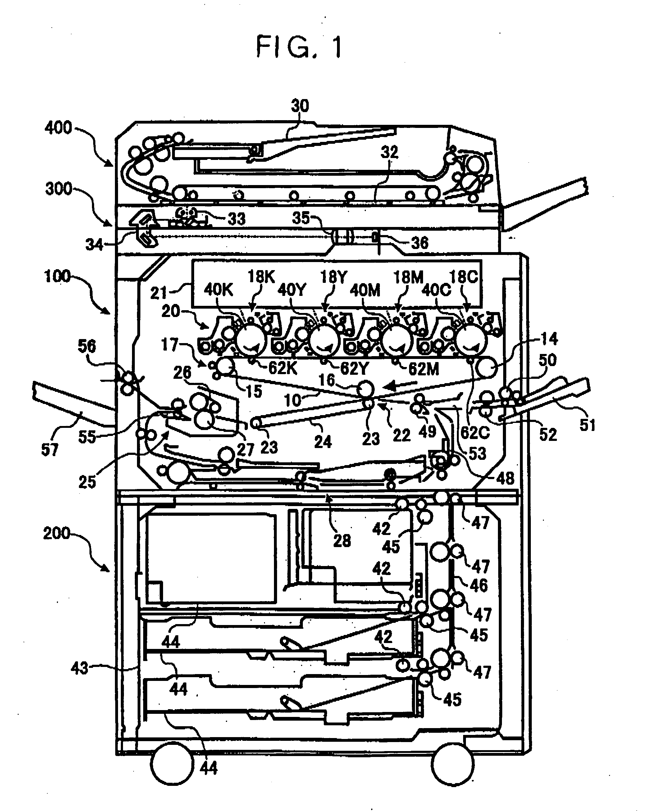
[0092]FIG. 1 is a schematic constitutional diagram showing the copier serving as an image forming apparatus which may be used as the detection subject of the abnormality determining apparatus to which the present invention is applied. The copier comprises image forming means constituted by a printer unit 100 and a paper feed unit 200, a scanner unit 300, and an original conveyance unit 400. The scanner unit 300 is attached to the top of the printer unit 100, and the original conveyance unit 400, constituted by an automatic document feeding device (ADF), is attached to the top of the scanner unit 300.

[0093] The scanner unit 300 reads...

second embodiment

[0271] The second embodiment mainly serves to achieve the aforementioned second object of the present invention.

[0272] Note that FIGS. 1 to 13 and 17 to 19 and the description pertaining to these drawings, which were referenced in the first embodiment, are also applied substantially to the second embodiment. Accordingly, repetitive description has been omitted, and the particular features of the second embodiment are described in detail.

[0273] First, the basic constitution of an abnormality determining apparatus according to the second embodiment will be described.

[0274] It is assumed that the detection subject of this abnormality determining apparatus is the same copier as that described up to this point, and that the abnormality determining apparatus determines the presence of an abnormality in the interior of the copier.

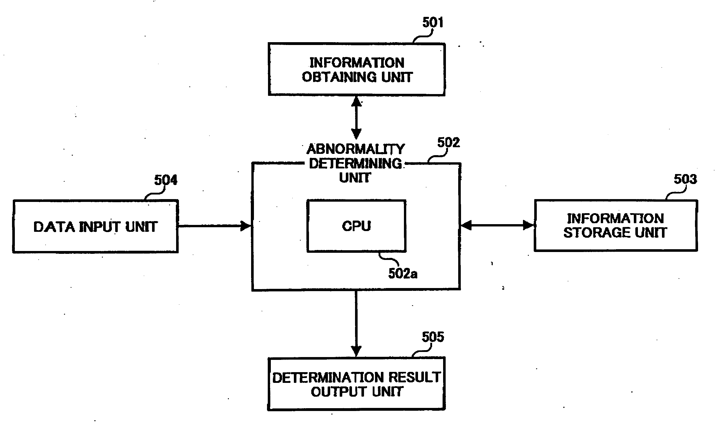
[0275] The constitution of the main parts of an electric circuit in this abnormality determining apparatus is shown in FIG. 21. As shown in the drawing, the a...

third embodiment

[0354] The third embodiment mainly serves to achieve the aforementioned third object of the present invention.

[0355] Note that FIGS. 1 to 3, 5 to 13, 17, and 18, and the description pertaining to these drawings, which were referenced in the first embodiment, are also applied substantially to the third embodiment. Accordingly, repetitive description has been omitted, and the particular features of the third embodiment are described in detail.

[0356]FIG. 37 shows the basic constitution of an abnormality predicting system comprising a state determining apparatus according to the third embodiment. A state determining apparatus 801 comprises an information obtaining unit 802 serving as information obtaining means, an index value calculation unit 803 serving as index value calculating means, and a determination unit 804 serving as change of state determining means. The information obtaining unit 802 obtains a plurality of types of information relating to an image forming operation of an ...


PUM


Abstract

An image forming apparatus is capable of specifying the type of an occurring abnormality to a certain extent while avoiding the increasingly complicated control that is caused when a plurality of abnormalities is detected individually according to the presence of their respective causes. A normal group data set, which is a collection of normal value combinations relating to grouped information constituted by a plurality of information of differing types, is stored in RAM or ROM serving as information storage means of a control unit. At least two or more sets of grouped information, comprising first grouped information constituted by a plurality of different types of information, and second grouped information constituted by a plurality of information in a different combination to that of the first grouped information, are obtained from the RAM, the ROM, various sensors, and an operation display unit. A CPU serving as determining means determines a Mahalanobis distance for each set of grouped information on the basis of the normal group data set and the obtained results of each set of grouped information, and uses this Mahalanobis distance to determine the presence of an abnormality according to categories.

Description

BACKGROUND OF THE INVENTION [0001] 1. Field of the Invention [0002] The present invention relates to an abnormality determining apparatus for determining the presence of an abnormality in a detection subject on the basis of stored information stored in information storage means, and a result obtained by information obtaining means for obtaining information about an object, and also to an abnormality determining method and an image forming apparatus. [0003] 2. Description of the Background Art [0004] In an image forming apparatus such as a copier, facsimile device, or printer, maintenance is required to replace consumables (toner, for example) and components (a photosensitive body, for example), repair faults, and so on. When a fault occurs, all or a part of the functions of the device must be halted from the occurrence of the fault to the completion of repairs, causing a great time loss for the user. It is therefore desirable to predict the occurrence of a fault in the image forming...

Claims


Application Information

Patent Timeline
IPC IPC(8): G06F3/12G06F11/30
CPCG06F3/121G06F3/1229G06F11/0754G06F11/0751G06K15/408
Inventor SHOJI, HISASHISATOH, OSAMUYAMADA, MASAAKIHIRAI, SHUJINAKAGAWA, YOSHINORITAKAHASHI, TOMOKOMIYAWAKI, KATSUAKISETO, TAKASHIMATSUURA, NEKKAOUCHI, SATOSHINAKAZATO, YASUSHI
Owner RICOH KK
Why Eureka
Try Eureka