Resonance type switching power source

Inactive Publication Date: 2005-07-21
SANKEN ELECTRIC CO LTD
View PDF9 Cites 42 Cited by
  • Summary
  • Abstract
  • Description
  • Claims
  • Application Information

AI Technical Summary

Benefits of technology

[0008] The resonance type switching power source according to the present invention, comprises a DC power source (1); a transformer (4) having primary and secondary windings (22, 23); at least first and second switching elements (2,3) connected in series to both electrodes of the DC power source (1); a current resonance capacitor (15) connected in parallel to the first switching element (2) and in series to the primary winding (22) of the transformer (4) and second switching element (3); a rectifying and smoothing circuit (5) connected to the second winding (23) of the transformer (4); and a control circuit (6) for producing drive pulses to the first and second switching elements (2,3) to alternately turn on and off the switching elements (2,3). A closed circuit is formed by the first switching element (2), primary winding (22) and current resonance capacitor (15) when the first switching element (2) is turned off. The control circuit (6) comprises a drive circuit (21) for supplying drive pulses to each control terminal of the first and second switching elements (2,3); a PWM circuit (9) for causing the drive circuit (21) to produce the drive pulses; an input voltage detector (7) for detecting input voltage from the DC power source (1) and comparing the input

Problems solved by technology

However, if input voltage varies in a wide range from 100 to 200 volts, time ratio or duty ratio λ for PWM control steeply changes without change in resonance frequency, but disadvantageously coin

Method used


Image

  • Resonance type switching power source
  • Resonance type switching power source
  • Resonance type switching power source

Examples


Embodiment Construction

[0021] Embodiments of the resonance type switching power source according to the present invention are described hereinafter in connection with FIGS. 1 to 10 wherein same symbols are applied to denote similar elements shown in FIGS. 1, 10 and 11.

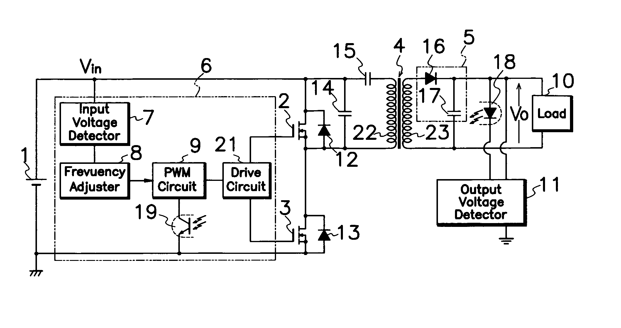
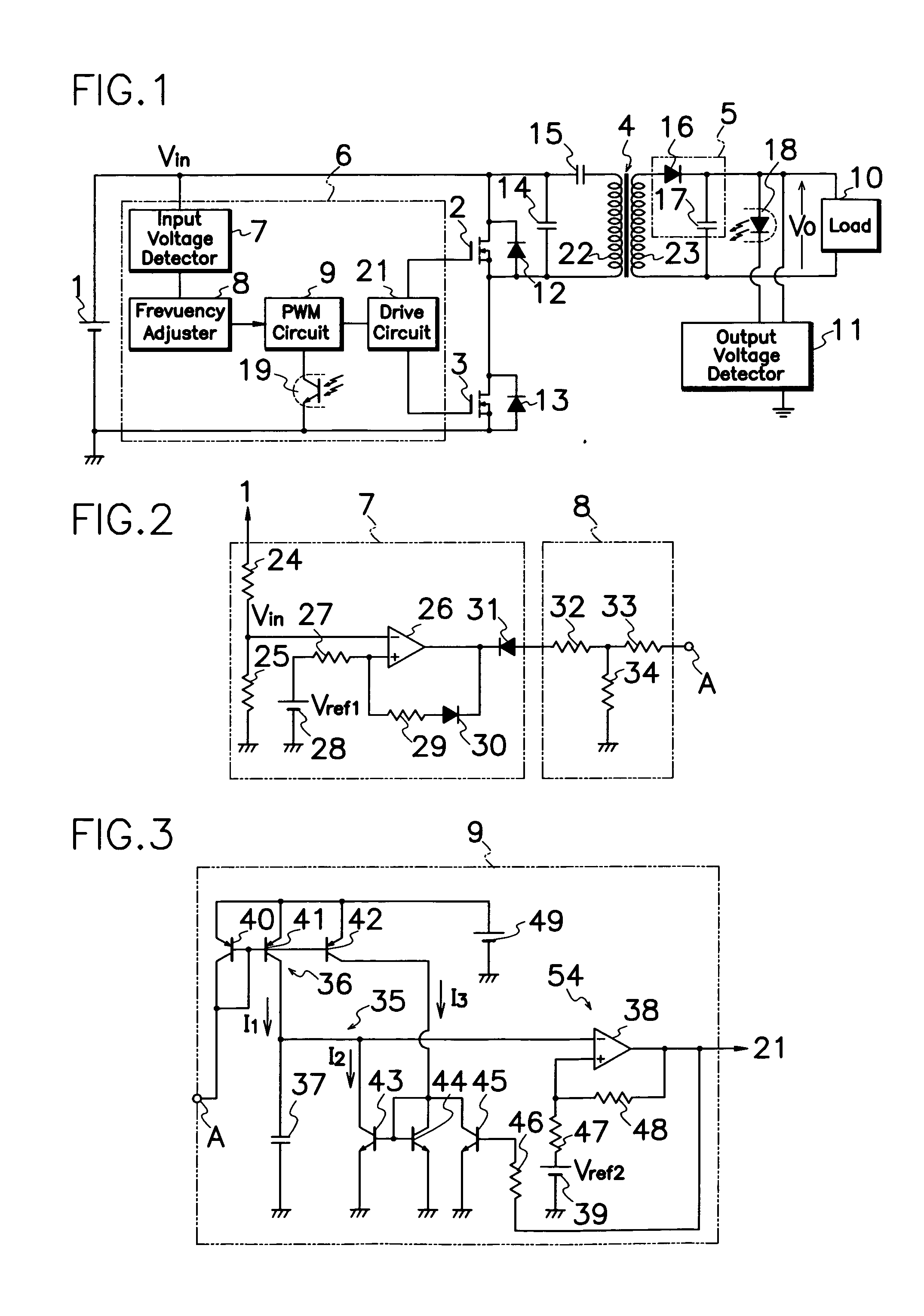
[0022] In an embodiment of the present invention shown in FIG. 1, the resonance type switching power source comprises a control circuit 6 which includes an input voltage detector 7 for detecting input voltage from DC power source 1 to produce detection signals; and a frequency adjuster 8 for adjusting the oscillation frequency of PWM circuit 9 in response to outputs from the input voltage detector 7 unlike prior art resonance type switching power source shown in FIG. 11. Input voltage detector 7 detects input voltage from DC power source 1 and compares input voltage and input reference voltage Vref1, and frequency adjuster 8 modifies oscillation frequency of PWM circuit 9 in response to output level from input voltage detector 7.

[0023] As ...


PUM


Abstract

A control circuit 6 of a resonance type switching power source comprises a drive circuit 21 for supplying drive pulses to each gate terminal of first and second MOS-FETs 2,3; a PWM circuit 9 for causing drive circuit 21 to produce drive pulses; an input voltage detector 7 for detecting input voltage from DC power source 1 and comparing the input voltage and input reference voltage Vref1; and a frequency adjuster 8 for adjusting oscillation frequency of PWM circuit 9 in response to output level from the input voltage detector 7. With adjustment in oscillation frequency of PWM circuit 9 in response to input voltage Vin from DC power source 1, control circuit 6 can modify on-off timing of first and second MOS-FETs 2, 3 to keep good resonating action and prevent off-resonance although DC power source 1 produces fluctuating input voltages.

Description

[0001] This invention relates to a resonance type switching power source, in particular, of the type capable of preventing off-resonance for good resonance action under a large fluctuation of input voltage. BACKGROUND OF THE INVENTION [0002]FIG. 11 shows an electric circuit diagram of a prior art resonance type switching power source. This power source comprises a DC power source 1 such as a battery or rectifier circuit of capacitor-input type; a transformer 4 having primary and secondary windings 22, 23; first and second switching elements 2, 3 such as MOS-FETs connected in series to both electrodes of DC power source 1; a series circuit of primary winding 22 of transformer 4 and a current resonance capacitor 15 connected in parallel to first switching element 2 and in series to second switching element 3; a rectifying and smoothing circuit 5 which comprises a rectifying diode 16 and a smoothing capacitor 17 connected to secondary winding 23 of transformer 4; an electric load 10 co...

Claims


Application Information

Patent Timeline
IPC IPC(8): H02M3/28H02M3/335
CPCH02M2001/0022H02M3/33569H02M1/0022H02M3/33571H02M3/01B60K28/10
Inventor OSAKA, SYOHEI
Owner SANKEN ELECTRIC CO LTD
Why Eureka
Try Eureka