Nuclear fusion reactor incorporating spherical electromagnetic fields to contain and extract energy

a technology of nuclear fusion reactor and electromagnetic field, which is applied in the direction of nuclear reactors, nuclear explosives, greenhouse gas reduction, etc., can solve the problem of no design for fusion reactors, and achieve the effect of avoiding the destruction of confinement devices

Inactive Publication Date: 2005-07-21
NORDBERG JOHN T
View PDF18 Cites 21 Cited by
  • Summary
  • Abstract
  • Description
  • Claims
  • Application Information

AI Technical Summary

Benefits of technology

[0026] The key to creating and maintaining the spherical electromagnetic confinement field is the use of spherical reactor cores and conductors. A key in creating harmonic fields is the careful design of electromagnetic induction coils that can be used to transfer energy to and from the containment circuit. In particular, the use of hemispheric coils promises to provide very clean harmonics at a relatively low cost. While there are many material and design variations possible in these designs, they all are intended to create powerful spherical electromagnetic fields around the fusion burn. In the past there has been no design for fusion reactors that places spherical electromagnetic fields around the fusion burn in order to impart energy to the fuel, to contain and ignite the fuel, and to extract energy from the fusion burn using MHD. These designs are the first to offer inexpensive, practically unlimited, almost totally clean energy.
[0036] There are major design differences between the spherical reactor designs of the present invention and MTF devices. MTF devices do not attempt to create a prolonged burn. Instead they are explosively imploded. MTF geometry is cylindrical or “quasi-spherical” rather than the true spherical designs of the present invention. Furthermore, MTF designs do not utilize an MHD process to either contain or extract energy from the fusion burn. Finally, the destruction of the MTF containment chamber is a distinguishing feature in comparison to the new designs of the present invention. In developing a commercially viable fusion reactor design, the spherical reactor designs of the present invention seek to avoid the destruction of the confinement device with each pulse.

Problems solved by technology

Second, the fusion burn is surrounded and wholly or partly contained by a spherical electromagnetic confinement field.
In the past there has been no design for fusion reactors that places spherical electromagnetic fields around the fusion burn in order to impart energy to the fuel, to contain and ignite the fuel, and to extract energy from the fusion burn using MHD.

Method used


Image

  • Nuclear fusion reactor incorporating spherical electromagnetic fields to contain and extract energy
  • Nuclear fusion reactor incorporating spherical electromagnetic fields to contain and extract energy
  • Nuclear fusion reactor incorporating spherical electromagnetic fields to contain and extract energy

Examples


Embodiment Construction

Overall Layout

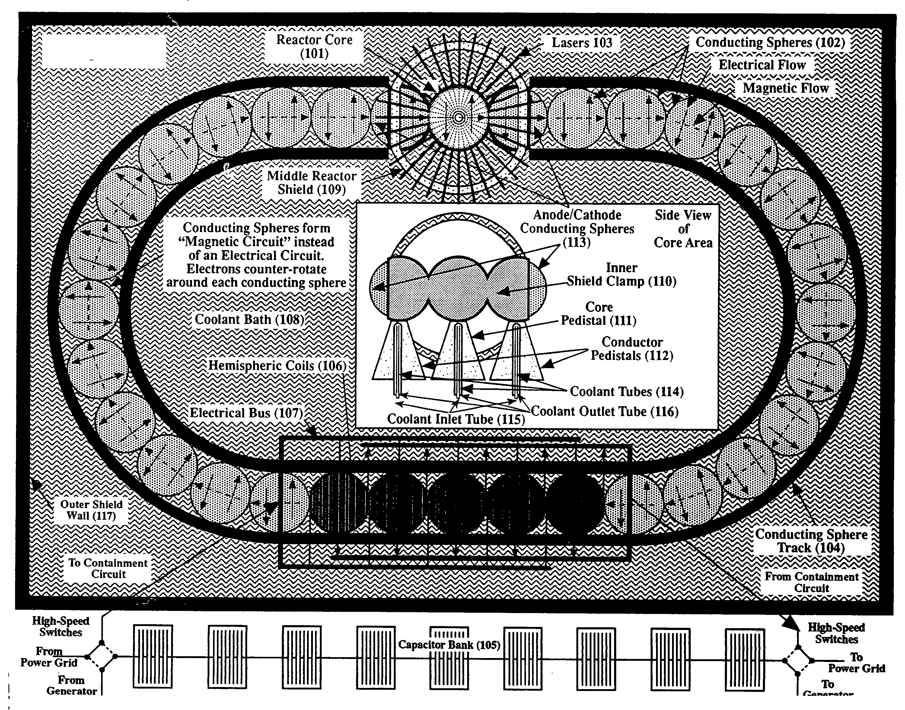
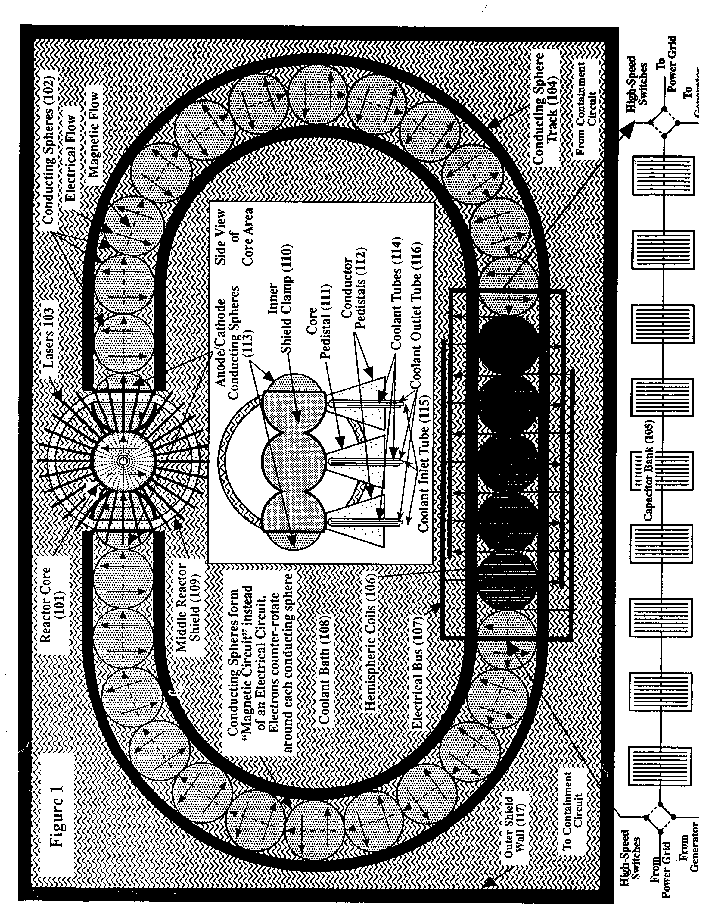
[0140] Refer now to FIG. 1, which is an overall drawing of the preferred embodiment of the present invention. It has one reactor core 101 and thirty-one conducting spheres 102 laid out in an oval pattern.

The Core

[0141] Reactor core 101 is a hollow sphere with many layers of conducting and non-conducting materials. The center of reactor core 101 is the intended location of the fusion reaction. The reaction may initially occur slightly offset from this center point but this does not affect the overall design. A main goal of the overall reactor design is to have fusion reactions occur at the center of the reactor core 101, and not to have fusion reactions occur at the centers of the conducting spheres 102. Therefore, conditions at the centers of the conducting spheres 102 are designed to inhibit nuclear fusion reactions.
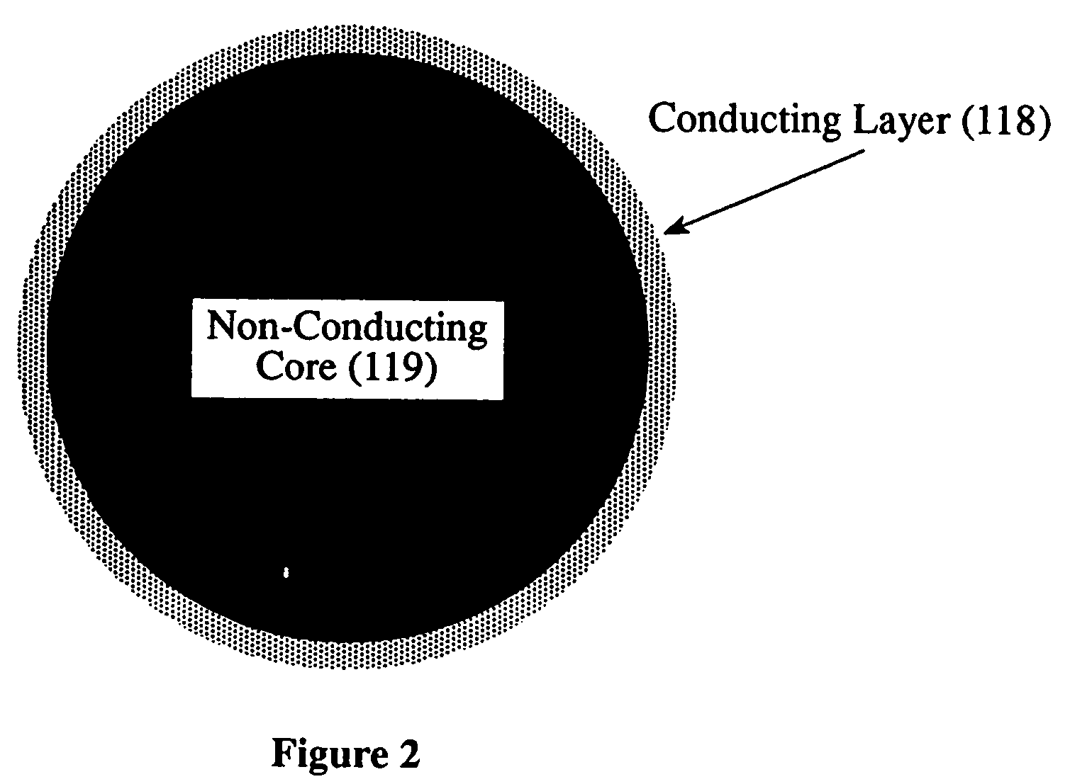
Conducting Spheres

[0142] The conducting spheres 102 in the preferred embodiment are completely solid as shown in FIG. 2. In other embodiments, the...


PUM


Abstract

A nuclear fusion reactor system includes a reactor core containing nuclear fusionable material and a plurality of conducting spheres arranged adjacent each other with at least two of said conducting spheres adjacent the reactor core. The reactor core and the conducting spheres form a electro / magnetic circuit such that fusion of fusionable material in the reactor core establishes an electro / magnetic flow around the electro / magnetic circuit. Preferably, a spherical electromagnetic confinement field is initiated around the reactor core such that fusion of the nuclear fusionable material generates a plasma which interacts with the spherical electromagnetic confinement field in a magnethydrodynamic manner. Preferably, electrical energy is inductively extracted in response to the electro / magnetic flow through a coil arrangement located around at least one of the conducting spheres.

Description

RELATED APPLICATIONS [0001] This application is a continuation of U.S. patent application Ser. No. 10 / 840,082, entitled “NUCLEAR FUSION REACTOR INCORPORATING SPHERICAL ELECTROMAGNETIC FIELDS TO CONTAIN AND EXTRACT ENERGY,” filed May 6, 2004, which claims priority to U.S. patent application Ser. No. 09 / 939,316, entitled “NUCLEAR FUSION REACTOR INCORPORATING SPEHERICAL ELECTROMAGNETIC FIELDS TO CONTAIN AND EXTRACT ENERGY,” filed Aug. 24, 2001 (now abandoned), which claims priority to U.S. Provisional Application No. 60 / 228,212, filed Aug. 25, 2000, all of which are herein incorporated by reference in their entirety.FIELD OF THE INVENTION [0002] The present invention relates to the field of commercial electric energy production. More particularly, the present invention is directed to methods and an apparatus for the production of electrical power via nuclear fusion reactors utilizing spherical electromagnetic fields to compress, contain and extract energy released during the fusion bur...

Claims


Application Information

Patent Timeline
Patent Type & Authority Applications(United States)
IPC IPC(8): G21B1/11
CPCG21B1/05Y02E30/126G21B1/11Y02E30/10
Inventor NORDBERG, JOHN T.
Owner NORDBERG JOHN T
Why Eureka
Try Eureka