Data transfer control device and electronic equipment

a control device and data transfer technology, applied in the direction of electrographic process equipment, still video cameras, instruments, etc., can solve the problem that the device cannot detect a normal state of the vbus voltage level, and achieve the effect of not being able to happen

Inactive Publication Date: 2005-07-21
SEIKO EPSON CORP
View PDF10 Cites 20 Cited by
  • Summary
  • Abstract
  • Description
  • Claims
  • Application Information

AI Technical Summary

Benefits of technology

[0005] Aspects of the invention can provide a data transfer control device that can switchover VBUS feed voltage and electronic equipment.

Problems solved by technology

In this way, it cannot be happened that the device erroneously detects a normal state of the VBUS voltage level as an abnormal state because the monitor of the VBUS normal voltage level is stopped.

Method used


Image

  • Data transfer control device and electronic equipment
  • Data transfer control device and electronic equipment
  • Data transfer control device and electronic equipment

Examples


Embodiment Construction

[0038] Exemplary embodiments of the invention will now be described in detail. It should be understood that the exemplary embodiments described below shall not limit nature of the invention which is described in claims. Also, all of components described in the embodiments below are not necessarily essential as a solution for the invention.

[0039] 1. Plug A and Plug B

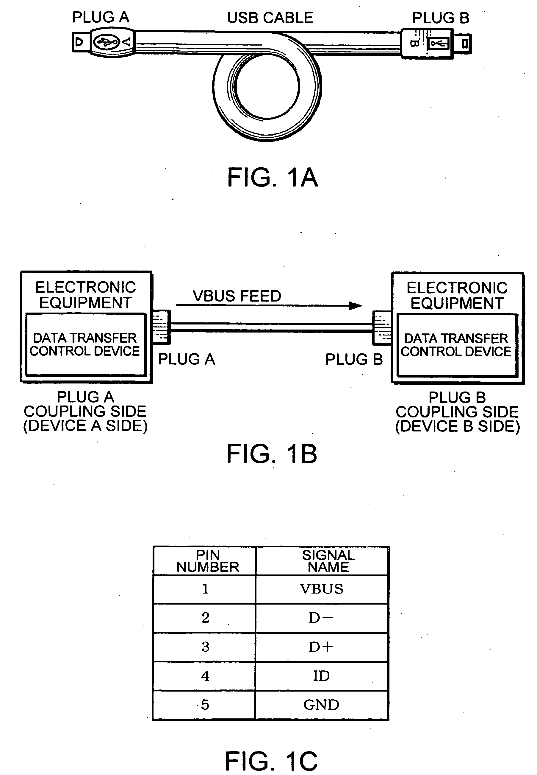
[0040] In the USB, as shown in FIG. 1A, a plug A and a plug B (a first plug and a second plug) are defined as connector standard. A receptacle A that has a structure in which the plug A can be inserted and a receptacle B that has a structure in which the plug B can be inserted are also defined. In addition, a mini-plug A, a mini-plug B, a mini-receptacle A and a mini-receptacle B are defined in order to reduce the size of the connector. Furthermore, in USB On-The-Go (OTG) which enables a peripheral (USB device) to have a simplified host function, a mini-receptacle AB in which both the plug A and the plug B can be insert...


PUM


Abstract

Aspects of the invention can provide a data transfer control device that can switchover VBUS feed voltage. The transfer controller can send a switchover request packet to switch over a VBUS feed voltage to a plug B coupling side (device B side). When the transfer controller receives a switchover consent packet, it can instruct a feed switch circuit to switch over from normal voltage feed to low voltage feed. Then, monitor of the VBUS normal voltage level can be stopped and monitor of the VBUS low voltage level is started. The transfer controller receives the switchover request packet to switch over the VBUS feed voltage from the plug A coupling side (device A side). If it agrees to the switchover, it can send the switchover consent packet. And then, the monitor of the VBUS normal voltage level can be stopped and the monitor of the VBUS low voltage level is started. The switchover request packet and the switchover consent packet can be sent by a control transfer.

Description

BACKGROUND OF THE INVENTION [0001] 1. Field of Invention [0002] Aspects of the invention can relate to a data transfer control device and electronic equipment. [0003] 2. Description of Related Art [0004] Related art universal serial bus (USB) standard has attracted attention as an interface standard for connections between personal computers and electronic equipment (peripheral equipment). Such USB has a feature of having a power supply line so-called “VBUS line” besides a data line. In the USB standard, a side to which plug A is coupled has to feed power using the VBUS line. However, portable electronic equipment, such as cellular phones generally works on batteries. Consequently, considering the battery drain, it is preferred to reduce its power consumption as much as possible even when the side to which plug A is coupled feeds power of VBUS. See, for example, Japanese Unexamined Patent Publication No. 2002-344537. SUMMARY OF THE INVENTION [0005] Aspects of the invention can provi...

Claims


Application Information

Patent Timeline
Patent Type & Authority Applications(United States)
IPC IPC(8): H04L29/00G03G15/16G06F13/40H04N1/00
CPCG06F13/4072H04N1/00236H04N1/00885H04N2201/0049H04N1/00901H04N1/00904H04N2101/00H04N1/00899
Inventor MATSUDA, KUNIAKI
Owner SEIKO EPSON CORP
Why Eureka
Try Eureka