
Linear compressor

a compressor and linear technology, applied in the direction of positive displacement liquid engines, mechanical equipment, pumps, etc., can solve the problems of difficult equipment production of effective gas bearings, significant frictional losses, and significant losses associated with the crank system that converts rotary motion, so as to reduce the external noise effect of vibration, reduce vibration, and increase the running speed

Inactive Publication Date: 2005-07-21
FISHER & PAYKEL APPLIANCES LTD
View PDF17 Cites 23 Cited by
  • Summary
  • Abstract
  • Description
  • Claims
  • Application Information

AI Technical Summary

Benefits of technology

[0010] It is an object of the present invention to provide a compact linear compressor which goes some way to overcoming the abovementioned disadvantages.

Problems solved by technology

However, even in their most efficient form, there are significant losses associated with the crank system that converts rotary motion to linear reciprocating motion.
Alternatively a rotary compressor which does not require a crank can be used but again there are high centripetal loads, leading to significant frictional losses.
However with normal manufacturing tolerances and equipment production of effective gas bearings is difficult.
However this arrangement would be too complex and costly for use in a commodity item such as a domestic refrigerator.
However this approach limits the operation of the compressor because the counterweight is a negative feedback device and is limited to the fundamental unbalance force.
However in implementing this design in a domestic refrigerator there is a problem when the piston mass is low.
This is a problem because the “third” vibration mode (where the piston and the cylinder vibrate in phase with each other but out of phase with the compressor shell) is only slightly above the desirable “second” mode (where the shell does not vibrate and the piston and cylinder are out of phase).

Method used


Image

  • Linear compressor
  • Linear compressor
  • Linear compressor

Examples


Embodiment Construction

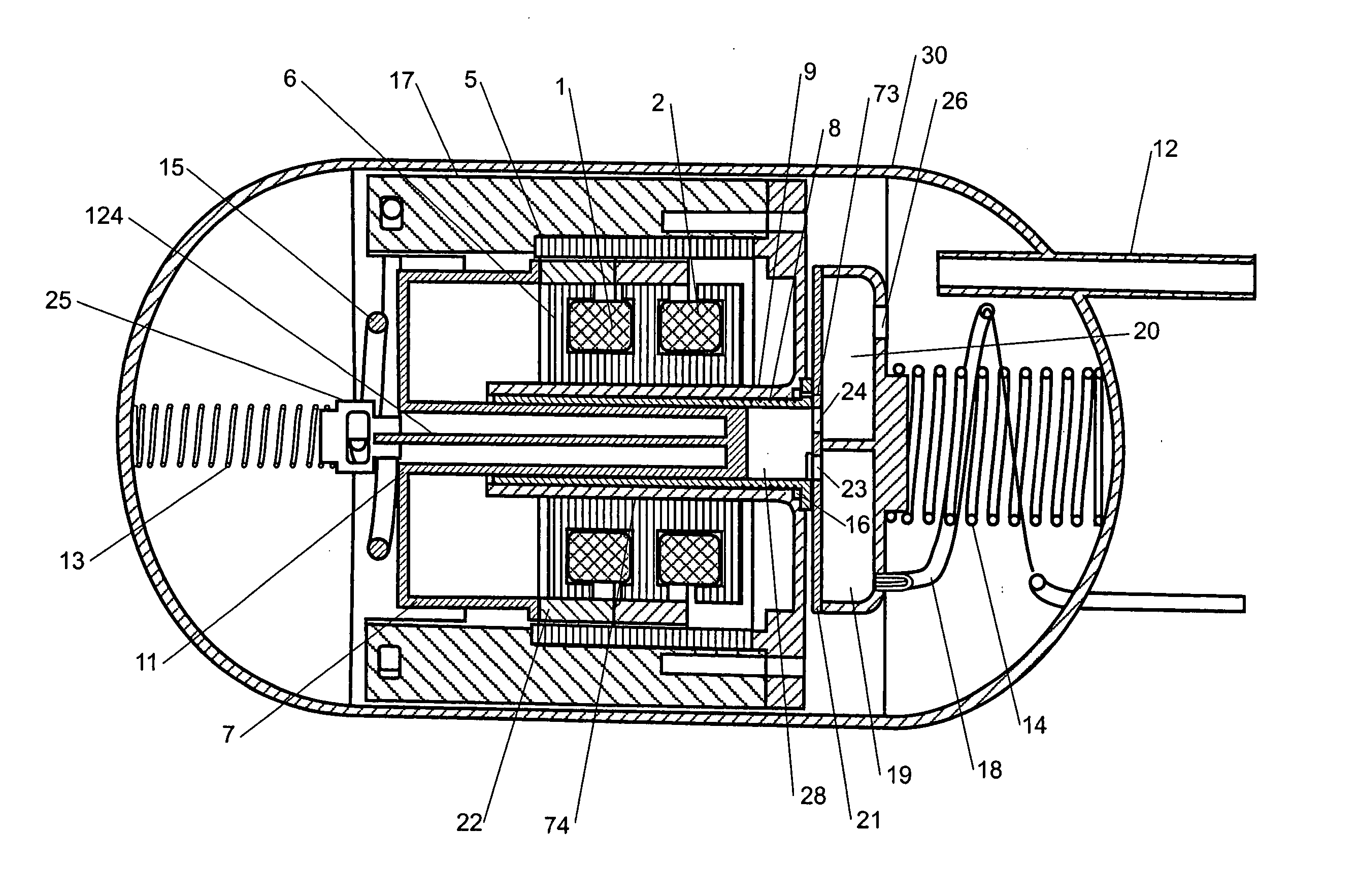
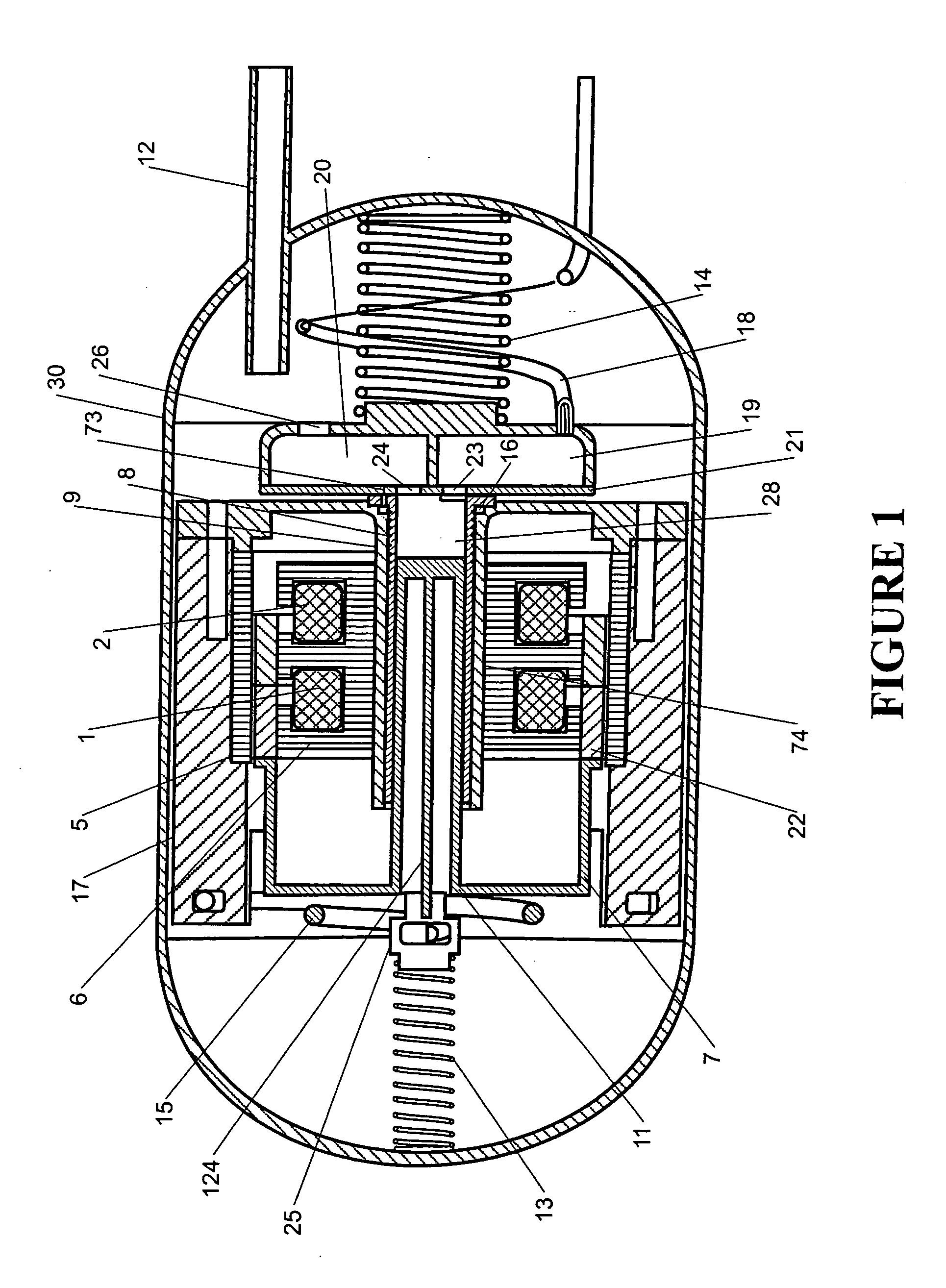
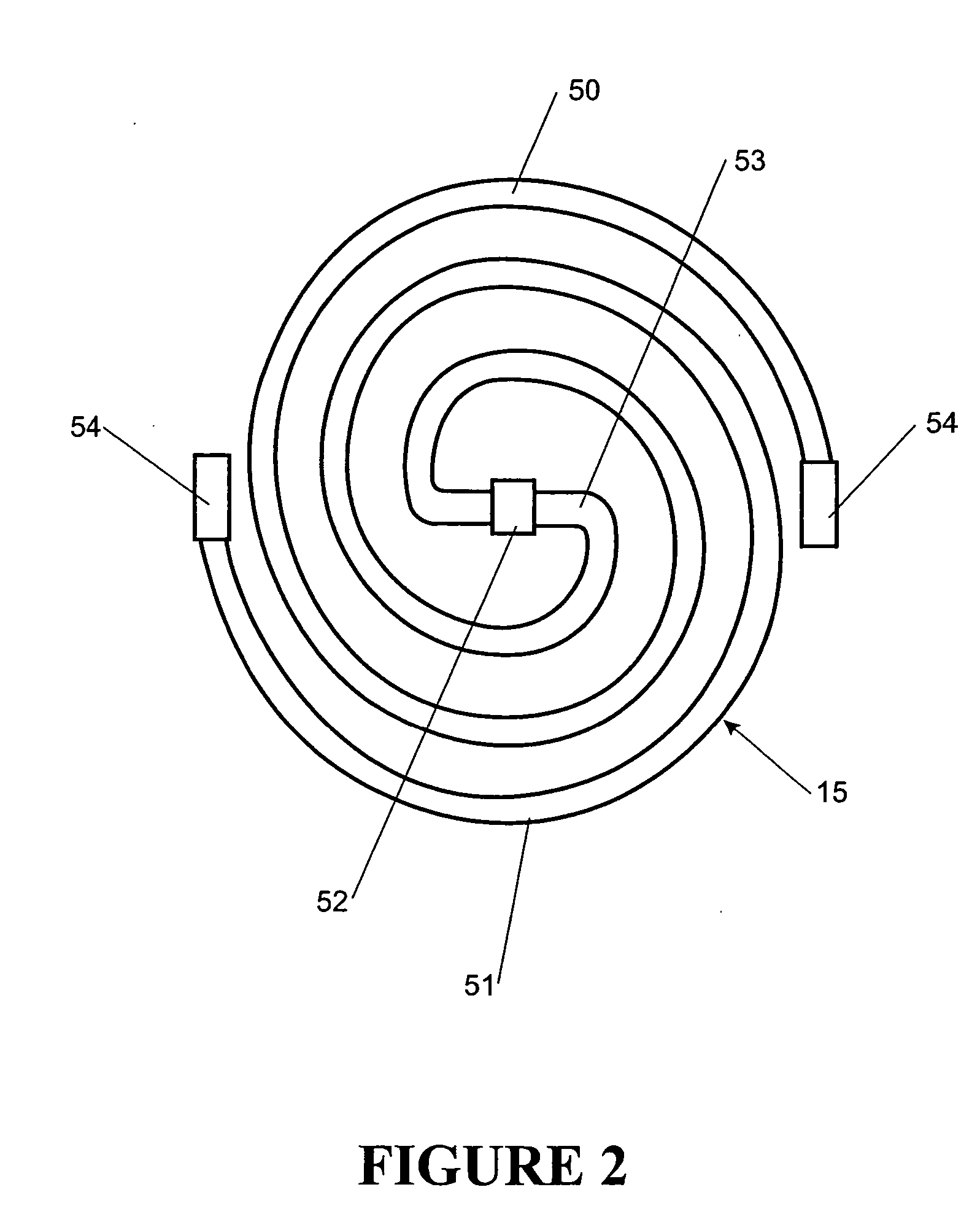
[0037] A practical embodiment of the invention, shown in FIG. 1, involves a permanent magnet linear motor connected to a reciprocating free piston compressor. The cylinder 9 is supported by a cylinder spring 14 and by a discharge tube 18 within the compressor shell 30. The piston 11 is supported radially by the bearing formed by the cylinder bore plus its spring 13 via the spring mount 25. A main spring 15 connects between the piston part 11 and the cylinder part 9. The total reciprocating movement is the sum of the movement of the piston 11 and the cylinder 9.

[0038] This reciprocating movement draws gas in through a suction tube 12 through a suction port 26 through a suction muffler 20 and through a suction valve port 24 in a valve plate 21 into a compression space 28. The compressed gas then leaves through a discharge valve port 23, is silenced in a discharge muffler 19, and exits through a discharge tube 18.

[0039] The cylinder 9 is supported by the discharge tube 18 and the cyl...


PUM


Abstract

A linear compressor includes a cylinder part and a piston part. A spring connects the cylinder part and the piston part and operates in the direction of reciprocation of the piston part relative to the cylinder part. The piston part includes a radially compliant but axially stiff linkage and piston. The cylinder part includes a cylinder and a cylinder liner therewithin. A bore runs through the cylinder liner and the piston reciprocates in the bore. Gas bearing passages are formed between the cylinder and the cylinder liner leading to opening through the wall of the cylinder liner to the bore. A gas bearing manifold receives compressed gases and supplies the compressed gases to the gas bearing passages. The gas bearing passages follow a tortuous path to the openings.

Description

[0001] This application is a divisional application of U.S. patent application Ser. No. 10 / 110,886, which was accorded a filing date under 35 U.S.C. §371 of Jul. 15, 2002, which is the National Stage of International Application No. PCT / NZOO / 00202 which has an international filing date of Oct. 17, 2000 and which was published in English on Apr. 26, 2001 under International Publication Number WO 01 / 29444.BACKGROUND TO THE INVENTION [0002] 1. Field of the Invention [0003] The present invention relates to a linear compressor, particularly but not solely for use in refrigerators. [0004] 2. Summary of the Prior Art [0005] Compressors, in particular refrigerator compressors, are conventionally driven by rotary electric motors. However, even in their most efficient form, there are significant losses associated with the crank system that converts rotary motion to linear reciprocating motion. Alternatively a rotary compressor which does not require a crank can be used but again there are hig...

Claims


Application Information

Patent Timeline
Patent Type & Authority Applications(United States)
IPC IPC(8): F04B35/04F16F1/02F04B39/00F16F1/04F16F1/06F16F1/10F16F1/12F16F15/067
CPCF04B35/045F16F1/025F16F1/04F16F15/067F16F1/10F16F1/123F16F1/06F04B17/04
Inventor ROKE, LINDSEY JACKMCGILL, IAN CAMPBELLDUNCAN, GERALD DAVIDFERGUSON, WILLIAM GEORGETAYLOR, ANDREW PAUL
Owner FISHER & PAYKEL APPLIANCES LTD
Features
  • Generate Ideas
  • Intellectual Property
  • Life Sciences
  • Materials
  • Tech Scout
  • Unparalleled Data Quality
  • Higher Quality Content
  • 60% Fewer Hallucinations
Learn More