Electrosurgical device with improved visibility

a technology of elongate members and surgical instruments, applied in contraceptive devices, applications, therapy, etc., can solve the problems of inability to precisely localize significant pain relief, and inability to accurately locate the conductive distal tip of the cannula, so as to improve the radiographic visualization of the elongate member, reduce the force required, and reduce the force

Inactive Publication Date: 2005-07-21
AVENT INC
View PDF60 Cites 31 Cited by
  • Summary
  • Abstract
  • Description
  • Claims
  • Application Information

AI Technical Summary

Benefits of technology

[0016] According to a further aspect of the present invention, a cannula for insertion into a patient's body is provided. The cannula optionally comprises an elongate member as well as means for improving the radiographic visualization of the elongate member. Optionally, the means for improving visualization is associated with the elongate member and may be shaped in such a way so as to reduce the force required to insert the cannula into the patient's body.
[0017] As a third aspect of the present invention, a system for delivering energy to a patient's body is provided. The system comprises (i) an energy source, (ii) a cannula comprising an electrically conductive elongate member having an electrically insulated region, an electrically exposed region, and a radiopaque marker for distinguishing the insulated region from the exposed region using radiographic imaging techniques, (iii) a means of delivering energy from the energy source to the cannula, and (iv) a reference electrode. The radiopaque marker may be shaped so as to reduce the force required to insert the cannula into the patient's body, for example by being tapered at its distal end.
[0018] In accordance with a further aspect of the present invention, a method for treating pain by delivering energy to a patient's body is described. The method optionally comprises the following steps: Providing an electrically conductive cannula, comprising an electrically insulated region, an electrically exposed region and a radiopaque marker for distinguishing the insulated region from the conductive region. The electrically exposed, and thus conductive, region of the cannula is optionally positioned at a location proximate a region of tissue to be treated. The position of the electrically exposed region of the cannula is optionally determined by identifying a location of the radiopaque marker using radiographic imaging, which identification may take place at least one of before and after the step of positioning the cannula. The method optionally further comprises a step of delivering energy via the cannula to the region of tissue to be treated in order to relieve pain. The radiopaque marker may be shaped to reduce the force required to insert the cannula into the patient's body. For example, the radiopaque marker may comprise a tapered distal end.
[0019] Thus, the present invention describes a novel cannula and methods of use thereof, wherein the cannula optionally overcomes some or all of the deficiencies associated with the prior art by incorporating a radiopaque marker to allow for improved visualization of at least a portion of the cannula utilizing radiographic imaging techniques such as fluoroscopy. In addition, the radiopaque marker is optionally structured to reduce the force required to insert the cannula comprising the radiopaque marker into a patient's body.

Problems solved by technology

This procedure is known as tissue denervation and it usually results in significant pain relief.
If the cannula, and through it the probe, is positioned incorrectly, the results for the patient can be disastrous, as the denervating energy may be applied to a region of tissue that should not be denervated.
One limitation of the technique used currently for RF denervation is that the insulated shaft of the cannula is indistinguishable from the exposed distal tip of the cannula under X-ray fluoroscopy, due to the fact that the entire cannula, i.e. both the insulated as well as the exposed regions, is generally made up of a radiopaque substance.
Therefore, precise localization of the conductive distal tip of the cannula is not possible as the entire cannula, comprising both the tip and the shaft, appears dark on the fluoroscopic image.
This increased force, in turn, may result in unnecessary damage to bodily tissue during insertion of such a device into a patient's body.

Method used


Image

  • Electrosurgical device with improved visibility
  • Electrosurgical device with improved visibility
  • Electrosurgical device with improved visibility

Examples


Embodiment Construction

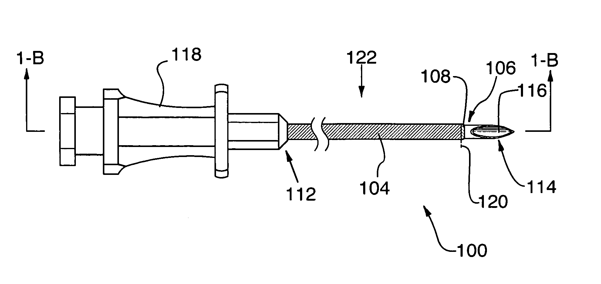
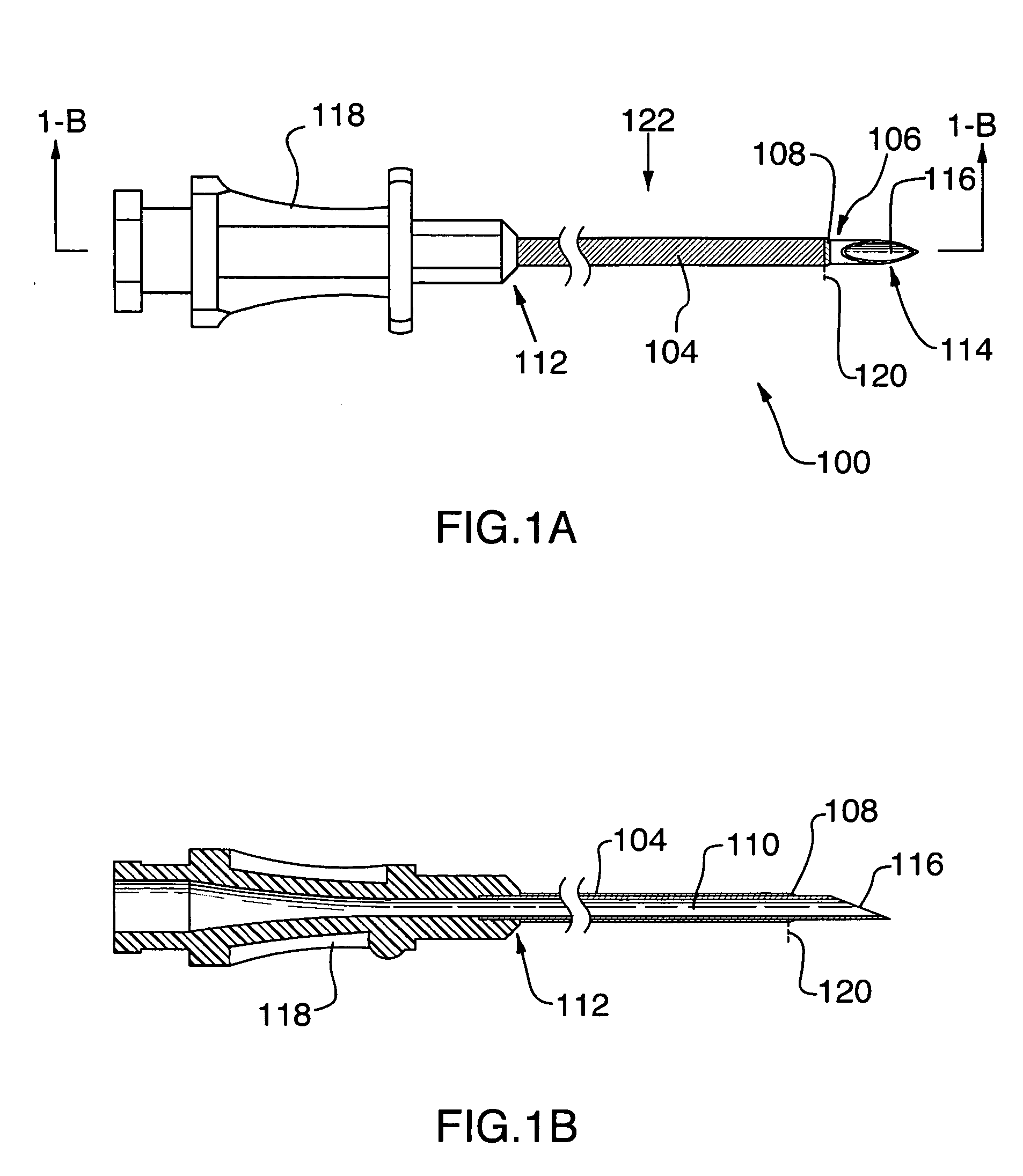
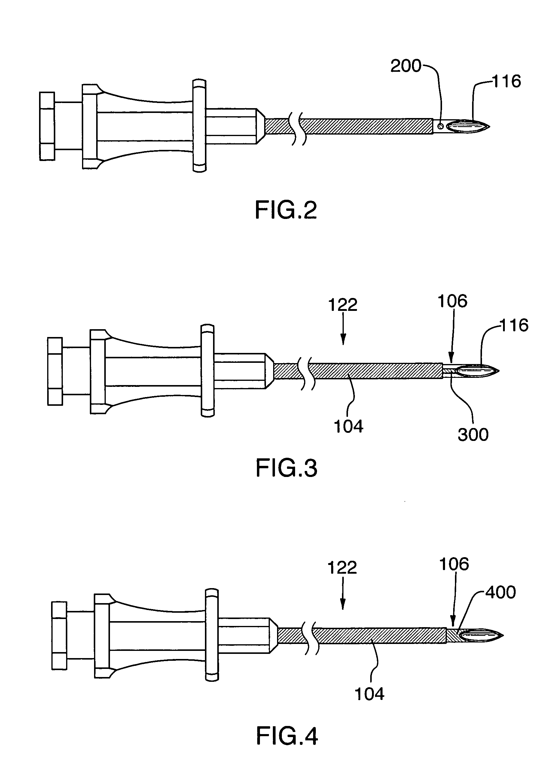
[0032] With specific reference now to the drawings in detail, it is stressed that the particulars shown are by way of example and for purposes of illustrative discussion of certain embodiments of the present invention only, and are presented in the cause of providing what is believed to be the most useful and readily understood description of the principles and conceptual aspects of the invention. In this regard, no attempt is made to show structural details of the invention in more detail than is necessary for a fundamental understanding of the invention, the description taken with the drawings making apparent to those skilled in the art how the several forms of the invention may be embodied in practice.

[0033] Before explaining at least one embodiment of the invention in detail, it is to be understood that the invention is not limited in its application to the details of construction and the arrangement of the components set forth in the following description or illustrated in the...


PUM


Abstract

A method and apparatus are disclosed for improving accuracy of placement of a cannula during delivery of electrical energy proximate to bodily tissue, e.g. neural structures. The apparatus optionally includes a cannula operable to deliver electrical current where a portion of the cannula is electrically insulated and a portion of the cannula is exposed and electrically conductive. The cannula further includes a radiopaque marker to identify a specific portion of the cannula, for example to differentiate the electrically insulated region from the electrically exposed region, by allowing it to be more clearly delineated using fluoroscopy or other radiographic imaging techniques. The radiopaque marker is optionally tapered in order to reduce the force required to insert a cannula comprising a radiopaque marker into the patient's body.

Description

CROSS-REFERENCE TO RELATED APPLICATIONS [0001] This application is a continuation-in-part of U.S. patent application Ser. No. 10 / 382,836, filed on Mar. 7, 2003.TECHNICAL FIELD [0002] The invention relates to an electrosurgical device and more specifically to a device used in the treatment of pain through the application of energy. BACKGROUND OF THE ART [0003] Chronic back pain is a cause for concern throughout the world and especially in the United States, affecting as many as 80% of all Americans at some point in their lives. Lower back pain can arise from any number of sources, including but not limited to conditions of the spinal vertebrae themselves, the intervertebral disks and the facet joints of the spine. Although the precise cause of back pain is still a matter of debate, it is recognized that nerves present in these structures contribute to the sensation and transmission of these pain signals. Some of the recent advances in the treatment of back pain, therefore, have focus...

Claims


Application Information

Patent Timeline
Patent Type & Authority Applications(United States)
IPC IPC(8): A61B18/14A61B19/00A61N1/06A61N1/34A61N1/40
CPCA61B18/1477A61B19/54A61B2019/5466A61N1/40A61N1/36017A61N1/36021A61N1/06A61B90/39A61B2090/3966
Inventor CHANDRAN, SUBASHINISHAH, KRISHAN
Owner AVENT INC
Why Eureka
Try Eureka