Method and device for production of a hollow section

a hollow section and production method technology, applied in the direction of manufacturing tools, machines/engines, transportation and packaging, etc., can solve the problems of restricted joining possibilities of round-bent tube parts to one or more components, and achieve the effect of improving the jointing capability of the hollow section to other components in a simple fashion

Inactive Publication Date: 2005-07-28
DAIMLER AG
View PDF8 Cites 49 Cited by
  • Summary
  • Abstract
  • Description
  • Claims
  • Application Information

AI Technical Summary

Benefits of technology

[0005] The underlying task of the invention is to modify a generic method so that the joining capability of the hollow section to other components is improved in simple fashion. In addition, an apparatus is to be shown with which this is made possible.
[0007] An appropriate contact surface for other components on which the component can be reliably fastened is created by embossing according to the invention of a secondary shaped element in the already-bent region before coiling of the preliminary shape to the final shape of the hollow section by a specially chosen contour of the element. Gluing, soldering and penetration joining are conceivable here as joining methods. Because of the possibility of permitting relatively large-surface joining, a large surface and therefore particularly durable joint can be created. The joining capability of the hollow section is therefore substantially improved in simple fashion. It is important here that the secondary shaped element be formed in the pre-bent region of the hollow section, since negligible deformations at best resulting from the coiling process develop there. The embossed secondary shaped element is therefore kept shape-true and contour-true to conclusion of the coiling process. Components that are to be joined to the secondary shaped element with the hollow section can be welded on much more durably by a contour of the secondary shaped element precisely adjusted to it than to a hollow section with unspecified shape. The formation need not necessarily be restricted to a single secondary shaped element; instead several secondary shaped elements can be produced both in the longitudinal direction of the hollow section and in the peripheral direction as long as this occurs in the pre-bent region of the hollow section. The secondary shaped element need not necessarily serve for joining of the hollow section to another component, for example an exhaust manifold with a flange or another exhaust pipe. It can just as well be used as a support for another component or to satisfy appearance or safety engineering aspects in vehicle construction.
[0009] In another preferred modification of the invention according to claim 3 and according to claim 8, following perforation, the perforation edge region is raised by means of a punch allocated to a corresponding device of the apparatus according to the invention, forming a collar enclosing the hole. By formation of a raised collar, a component to be added onto the hollow section, which is designed as a gas or fluid conducting line, can be mounted in simple fashion onto the collar, during which the line finds a secure stop on the hollow section at the location of the secondary shaped element, especially when formed as a flat site. The hollow section can now be welded to the line. If welding proves to be difficult for any accessibility reasons, the line can also be mounted only over part of the collar so that the line can be simply welded to the collar by a continuous fillet weld. Depending on the length of the raised collar it is also conceivable to join the collar to the line via a sleeve or shell. Simple insertion of the line without welding is also conceivable, forming a small or even large annular gap so that a sliding seat is formed between the hollow section and line.
[0010] In a particularly preferred embodiment of the apparatus according to the invention according to claim 10, the perforation device is integrated in the embossing device. By reducing the number of tools by combining two normally separate tools in a single tool, not only are enormous costs saved, but so is time required by the individual tools for the opening and closing movements and the manufacturing time for the hollow section is therefore significantly shortened. In addition, manufacturing tolerances are minimized during production, which can result from transport to another work station and introduction into the tool there.
[0011] In another particularly preferred modification of the apparatus according to the invention according to claim 11, the device for raising a collar enclosing the hole is integrated in the embossing device. Advantages resulting from the aforementioned integration are also produced here so that in conjunction with integration of the perforation device in the embossing device, manufacturing tolerances are additionally reduced and production costs and production time are minimized by this further innovation. In addition, the costs for transport logistics are fully eliminated.

Problems solved by technology

The round-bent tube part, however, is restricted in its joining possibilities to one or more components, since the tube part can only be reliably and securely joined on its ends by plug connections or fillet welds to other components.

Method used


Image

  • Method and device for production of a hollow section
  • Method and device for production of a hollow section
  • Method and device for production of a hollow section

Examples


Embodiment Construction

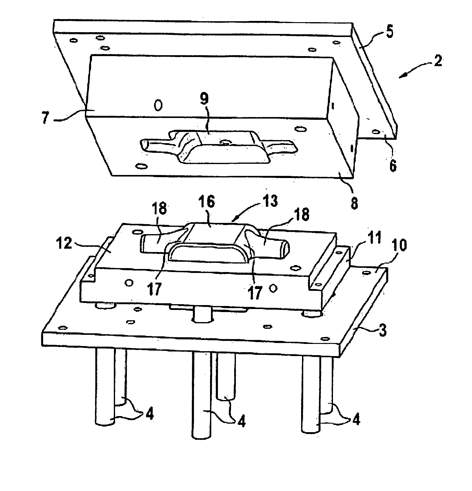
[0024] Parts of an apparatus for the production of a hollow section 1 (FIG. 8) are shown in FIGS. 1 to 7, which is formed in a first working step from a flat sheet or a coiled sheet to an unwound pre-shape of the hollow section 1 by deep drawing with a deep-drawing device 2 (FIG. 1). The deep-drawing device 2 consists essentially of a press table 3, which is mounted on several columns 4, and a press head 5 which can be driven hydraulically or pneumatically to make lifting movements. An upper die 7 having a cavity 9 on its bottom 8 whose contour corresponds to the unwound pre-shape of hollow section 1 is arranged on the bottom 6 of the press head. On the top 10 of press table 3 a lower die 11 is fastened whose top 12 has the counter shape 13 to cavity 9. According to the finished pre-shape of hollow section 1, which is formed as a tube piece 14 with a by-pass connector 15 extending radially from it, the counter shape 13 protruding from the top 12 of lower die 11 has an elongated flat...


PUM

PropertyMeasurementUnit
pre-shapeaaaaaaaaaa
shapeaaaaaaaaaa
durableaaaaaaaaaa

Abstract

The invention concerns a method and apparatus for production of a hollow section (1) in which a coiled pre-shape of the hollow section (1) is deep drawn from a sheet part, which is pre-bent after a trimming process and coiled into the final shape of hollow section (1). The edges (45) of hollow section (1) lying in the peripheral direction are then joined together in the contact region. In order to improve the joining capability of hollow section (1) to other components in simple fashion, it is proposed that before the coiling process at least one flat site (35) for joining to another component be embossed before the coiling process in a pre-bent region of the hollow section (1).

Description

BACKGROUND OF THE INVENTION [0001] 1. Field of Invention [0002] The invention concerns a method for production of a hollow section according to the preamble of patent claim 1 and a device for this purpose according to the preamble of patent claim 6. [0003] 2. Related Art of the Invention [0004] A generic method and a generic device are known from DE 195 48 224 A1. The hollow section described therein is designed as a tube part with a bypass connector and serves as an exhaust manifold pipe for a vehicle exhaust system. The tube part is deep-drawn from a sheet coil or plate blank in a multi-purpose composite die. After subsequent trimming of the deep-drawn shape, a tube part semi-finished product is produced, which corresponds to the finished shape of the tube part end product. This semifinished product is bent and coiled in subsequent process steps in the multipurpose composite die. The finally bent coiled part is then welded to become gas-tight on its edges lying in the peripheral d...

Claims


Application Information

Patent Timeline
Patent Type & Authority Applications(United States)
IPC IPC(8): B21C37/29B21D35/00B21D53/88F01N13/08F01N13/18
CPCB21C37/296F01N13/08F01N13/18Y10T29/53417Y10T29/49908Y10T29/49398Y10T29/49442
Inventor BIEN, WILFRIEDHALVES, MICHAELHULSBERG, THOMASKLUSSMANN, UWEMULLER, BERNHARDNUHN, HOLGERPUNJER, RALFREINHARDT, OLAVRIEWERT, DIRKRIGGERS, ALFREDSTERNAL, THORSTEN
Owner DAIMLER AG
Why Eureka
Try Eureka