Hand tool

a technology of hand tools and return springs, applied in the field of hand tools, can solve the problems of not being able to mount back, being considered impractical or uncomfortable with a return spring, and many users who do not want the function of the return spring

Inactive Publication Date: 2005-07-28
KAPMAN
View PDF4 Cites 5 Cited by
  • Summary
  • Abstract
  • Description
  • Claims
  • Application Information

AI Technical Summary

Benefits of technology

[0015] According to further features the invention is characterized in that the leg that is opposite to the leg provided with the sleeve including said guides comprises a recess in which the free end part of the spring part is able to move freely when the spring ...

Problems solved by technology

It has been found, however, that many users do not at all want the return spring function.
This may be due to old habits; one is simply used to a tool without a return spring and then it is considered impractical or uncomfortable with a return spring.
Then the user often removes the return spring from the tool and it can usually not be mounted back again.
In other cases it may be such that the return spring function is in itself wanted but one believes that it is impractical to place the tool in one's pocket or tool box with the legs splayed apart and where the legs easily hook up with other tools making it difficult to take the tool up again or to take other tools up from the box.
Besides, it is definitely not anything that...

Method used


Image

  • Hand tool
  • Hand tool
  • Hand tool

Examples


first embodiment

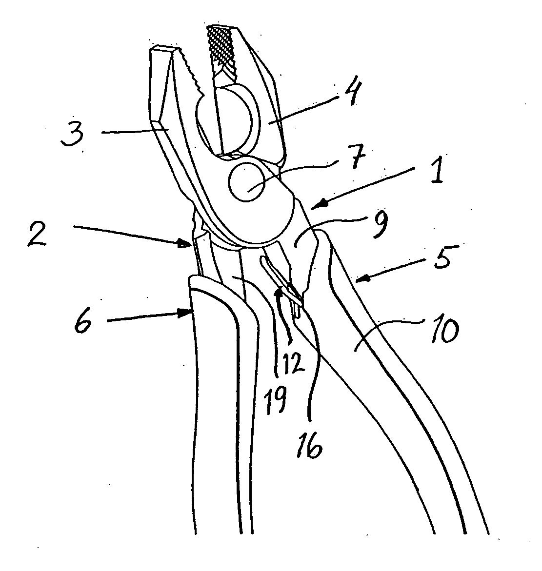
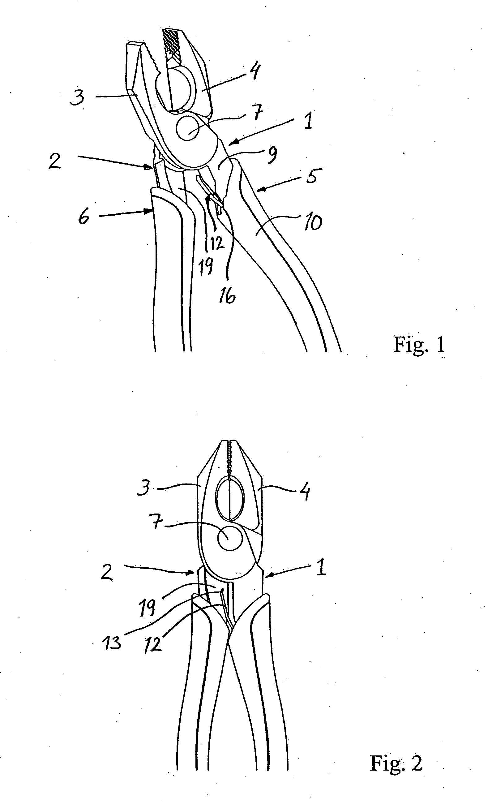
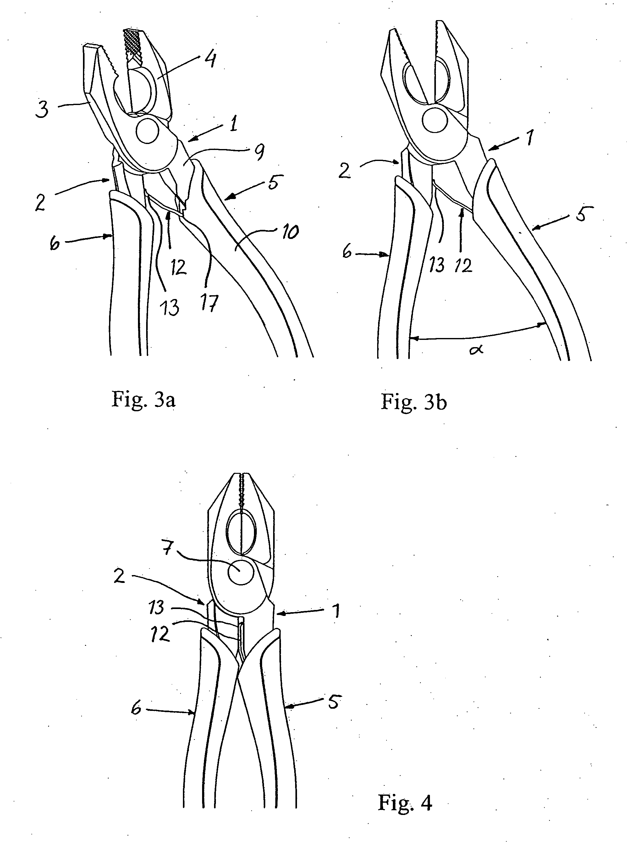
[0027] According to the present invention the spring is able to take an active position and an inactive position. This can be achieved by providing the sleeve illustrated in FIGS. 1-5 with guides 16, 17 that define two spring positions. As will clearly be seen from the enlarged view of FIG. 5 the first guide 16 defines a first inactive position for the spring 12. The second guide 17 defines a second position for the spring 12 which is an active position. The inactive position is also illustrated in FIGS. 1 and 2, where the guide 16 and the placement of the spring in the inactive position is especially evident from FIG. 1. The active position is also illustrated in FIGS. 3a, 3b and 4, where the guide 17 will be especially evident from FIG. 3a.

[0028] The two guides 16 and 17 are, according to the first embodiment, executed as two grooves provided on the inside of the sleeve 10, i.e. the inner surface facing the inner part 9 of the gripping part. The two positions for the spring 12 a...

second embodiment

[0030] In FIG. 6 it is illustrated the present invention and in enlargement. According to this embodiment the sleeve has three guides 16, 17, 18 that each defines a position for the spring 12 by abutment in the grooves that form the guides. Of these positions the first position, determined by the first guide 16, is an inactive position. In FIG. 6 the spring 12 is in this position. The next position, the second position defined by the second guide 17, is an active position that gives a certain opening angle between the legs 1, 2. The third position, defined by the guide 18, is a further active position for the spring 12 that gives another, larger opening angle compared to the guide 17. In the same way as above the spring 12 may easily be moved between the different positions by a movement sideways, or as an alternative upwards and sideways, which movement may for instance be executed with the aid of the thumb of the user. In this way it is possible to arrange different opening angles...


PUM


Abstract

The invention relates to a hand tool comprising a first leg (1) and a second leg (2) whereby a front part of the respective leg creates a tool part (3 and 4 respectively) and a rear part of the respective leg creates a gripping part (5 and 6 respectively). The gripping part (5) of at least one of the legs comprises an outer part in the form of a sleeve (10) which is fitted over an inner part (9) connected with the tool part (3). Further the hand tool comprises at least one spring part (12) with a first freely moveable end part (13) and a second end part firmly held at the mentioned sleeve (10). This spring part (12) is intended to again move the legs (1, 2) apart after they have been squeezed together in using the tool. According to the invention the mentioned sleeve (10) of one of the mentioned legs is executed with guides (16, 17, 18) for at least two positions for the spring part (12), of which a first guide (16) defines the first position which is an inactive position for the spring part (12) where it does not exert any separating force upon the legs (1, 2) in use and a second guide (17, 18) defining a second position which is an active position for the spring part (12), where it exerts a separating force upon the legs (1, 2) in use as a result of the first free end part (13) of the spring part coming into abutment with the opposite leg.

Description

[0001] The present invention concerns a hand tool with two legs in accordance with the preamble of the patent claim 1. More particularly, the invention concerns different kinds of pliers, but also other types of hand tools are conceivable. BACKGROUND OF THE INVENTION [0002] Hand tools, such as for example pliers, sheet-metal shears and pruning shears that are provided with a so called return spring between the two legs of the tool handle are previously known. This return spring functions in such a way that when the two legs are squeezed together in using the pliers the mentioned spring will exert a leg separating force, and the legs will therefore be re-opened to a given angle as soon as the squeezing force ceases. The return spring may be a helical spring or different types of leaf spring. [0003] It has been found, however, that many users do not at all want the return spring function. This may be due to old habits; one is simply used to a tool without a return spring and then it i...

Claims


Application Information

Patent Timeline
IPC IPC(8): B25B7/18
CPCB25B7/18
Inventor LOVEMARK, MATTIASOL-LARS, JAN
Owner KAPMAN
Why Eureka
Try Eureka