
Stencil printing machine

Inactive Publication Date: 2005-07-28
RISO KAGAKU CORP
View PDF2 Cites 0 Cited by
  • Summary
  • Abstract
  • Description
  • Claims
  • Application Information

AI Technical Summary

Benefits of technology

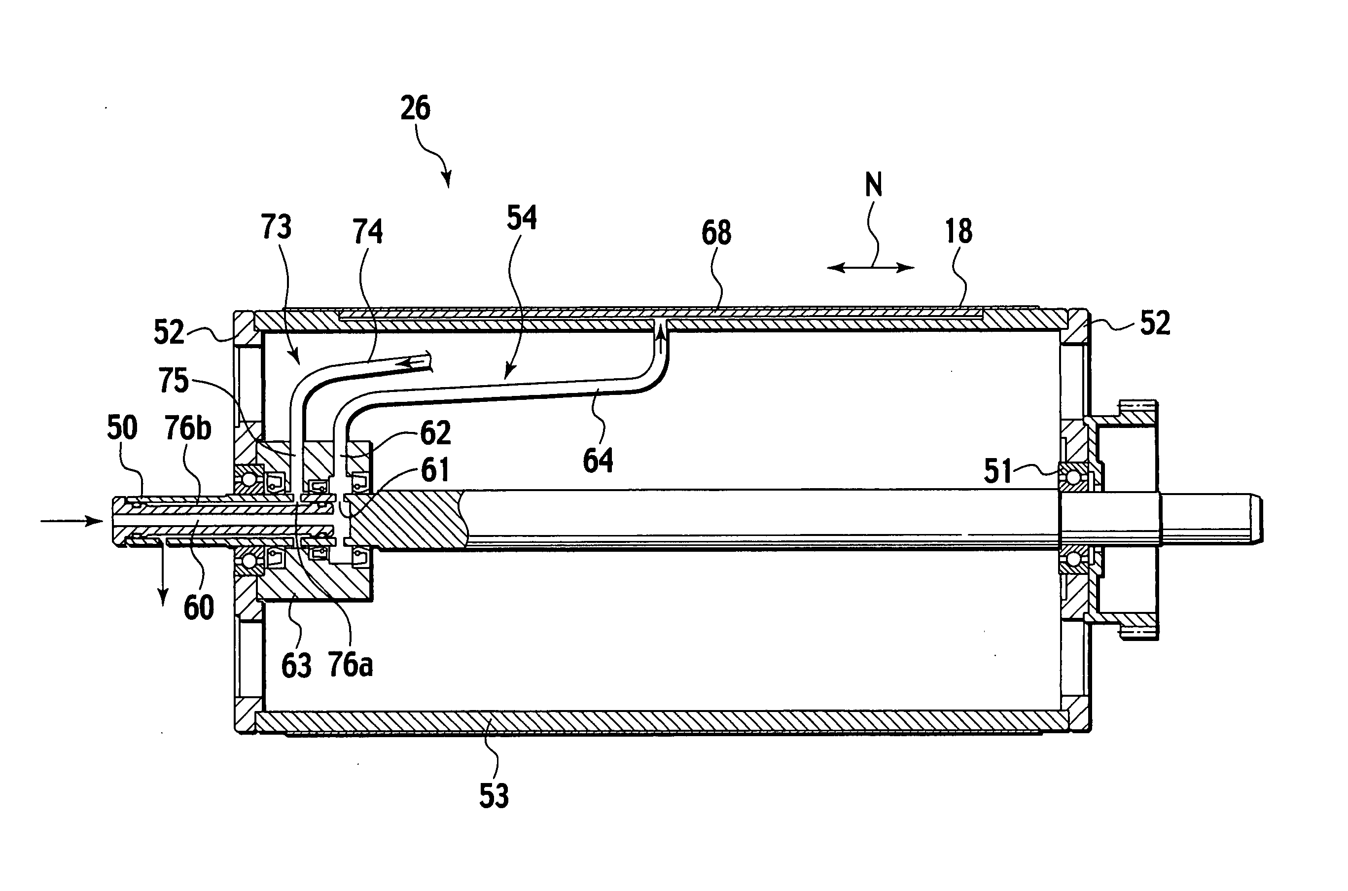
[0018] In this connection, the applicant of the present invention has proposed a stencil printing machine, which includes: a drum which is freely rotatable and has an outer peripheral wall formed of an ink impermeable member, in which a stencil sheet is mounted on a surface of the outer peripheral wall; an ink supply device which has an ink supply port on the outer peripheral wall of the drum, and supplies ink to the surface of the outer peripheral wall from the ink supply port; and a pressure roller which presses a print medium fed thereto to the outer peripheral wall. In this stencil printing machine, when the print medium is fed thereto in a state where the outer peripheral wall of the drum is rotated and the ink is supplied to the surface of the outer peripheral wall from the ink supply port, the print medium is conveyed while being pressed to the stencil sheet and the outer peripheral wall of the drum by the pressure roller. Meanwhile, the ink between the outer peripheral wall of the drum and the stencil sheet is diffused downstream in a printing direction while being squeezed. Moreover, the ink thus diffused oozes out of perforations of the stencil sheet to be transferred to the print medium side, and an ink image is printed on the print medium. Accordingly, the ink supplied to the drum is held in a substantially enclosed space between the outer peripheral wall of the drum and the stencil sheet, and is restricted from being brought into contact with the atmosphere as much as possible. Hence, degradation of the ink can be prevented as much as possible even if the printing is not performed for a long time.
[0020] In this connection, it is an object of the present invention to provide a stencil printing machine capable of restricting ink clogging of the ink supply port and the degradation of the ink in a type including the ink supply port on the outer peripheral wall of the drum.
[0022] According to the above-described configuration, when the drum is stopped, the ink supply port is closed by the first cap device, thus making it possible not to bring the ink in the ink supply port into contact with the atmosphere. Hence, ink clogging and degradation of the ink at the ink supply port can be restricted.
[0024] According to the above-described configuration, when the drum is stopped, the ink return port is closed by the second cap device, thus making it possible not to bring the ink in the ink return port into contact with the atmosphere. Hence, ink clogging and degradation of the ink at the ink return port can be restricted.
[0026] According to the above-described configuration, the first cap device can be installed without involving a design change of the drum. Hence, the first cap device can be easily installed in the existing stencil printing machine.
[0028] According to the above-described configuration, the second cap device can be installed without involving the design change of the drum. Hence, the second cap device can be easily installed in the existing stencil printing machine.

Problems solved by technology

However, in the stencil printing machine described above, the ink supply port is open to the outer peripheral wall of the drum, and this ink supply port is not always completely protected from the contact with the atmosphere even in a state of being covered with the stencil sheet.
Accordingly, such possibilities cannot be denied that the ink is cured by the contact with the atmosphere to clog the ink supply port, that the ink is degraded, and so on.

Method used


Image

  • Stencil printing machine
  • Stencil printing machine
  • Stencil printing machine

Examples


Embodiment Construction

[0037] An embodiment of the present invention is described below based on the drawings.

[0038] As shown in FIG. 4, a stencil printing machine is mainly composed of an original reading unit 1, a stencil making unit 2, a printing unit 3, a paper feed unit 4, a paper discharge unit 5, and a stencil disposal unit 6.

[0039] The original reading unit 1 includes an original setting tray 10 on which an original to be printed is mounted, reflective-type original sensors 11 and 12 which detect the presence of the original on the original setting tray 10, original conveyer rollers 13 and 14 which convey the original on the original setting tray 10, a stepping motor 15 which rotationally drives the original conveyer rollers 13 and 14, a contact image sensor 16 which optically reads image data of the original conveyed by the original conveyer rollers13 and 14 and converts the read data into electrical signals, and an original discharge tray 17 on which the original discharged from the original s...


PUM


Abstract

A stencil printing machine includes: a drum which is freely rotatable and has an outer peripheral wall formed of an ink impermeable member, in which a stencil sheet is mounted on a surface of the outer peripheral wall; an ink supply device which has an ink supply port on the outer peripheral wall of the drum, and supplies ink to the surface of the outer peripheral wall from the ink supply port; a pressure roller which presses a print medium fed thereto to the outer peripheral wall; and a first cap device capable of closing the ink supply port. Moreover, the stencil printing machine further includes: an ink return device which has an ink return port on the outer peripheral wall, and returns the ink which flows into the ink return port; and a second cap device capable of closing the ink return port.

Description

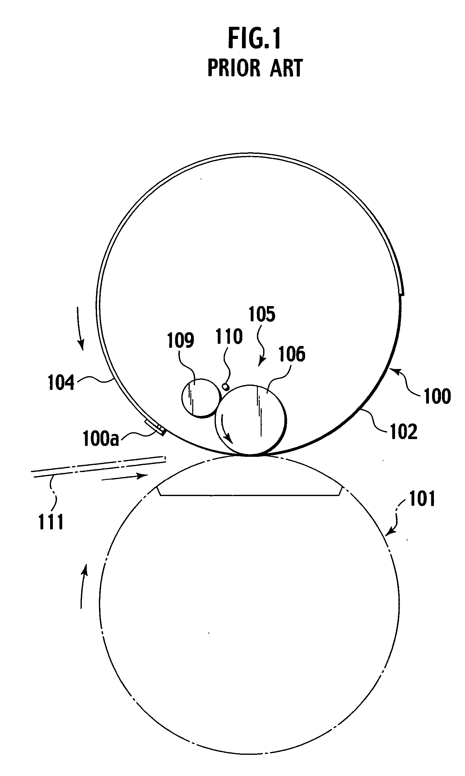
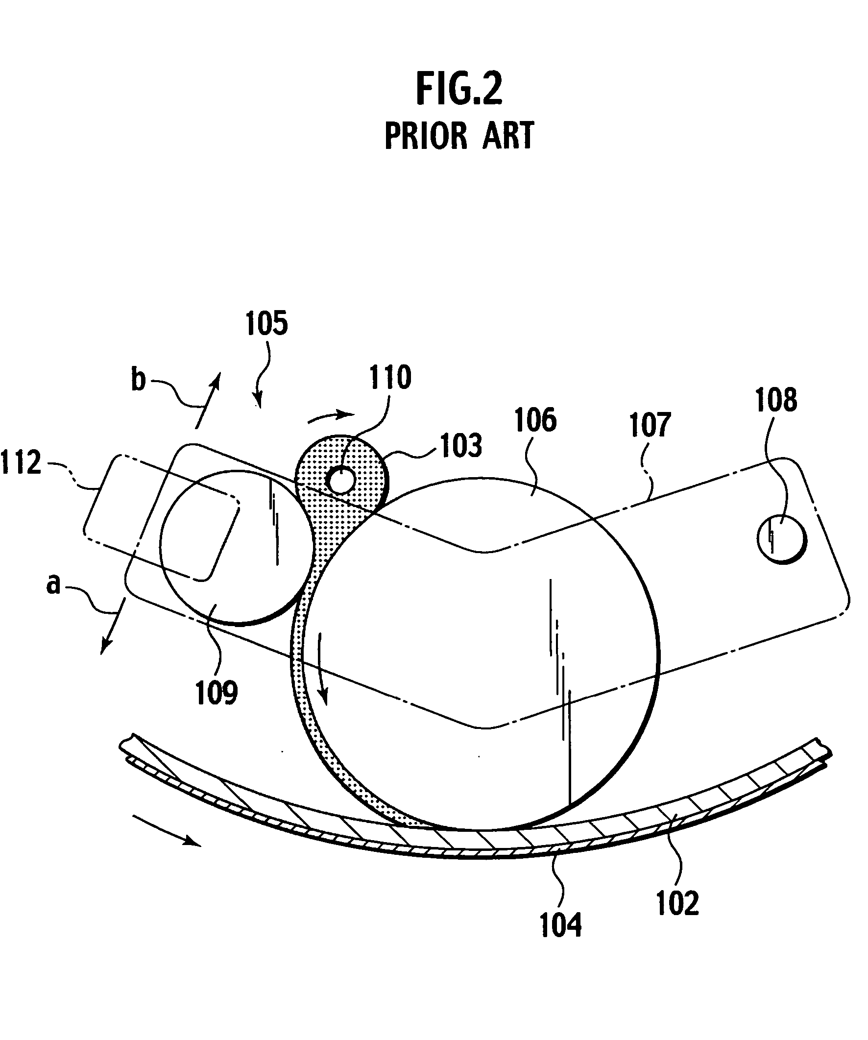
BACKGROUND OF THE INVENTION [0001] 1. Field of the Invention [0002] The present invention relates to a stencil printing machine which conveys a print medium while pressing the print medium to a drum on which a stencil sheet is mounted, and transfers ink oozing from perforations of the stencil sheet onto the print medium. [0003] 2. Description of the Related Art [0004] As a conventional printing method of a stencil printing machine, there are an inner press method (refer to Japanese Patent Laid-Open Publication No. Hei 7-132675 (published in 1995)) and an outer press method (refer to Japanese Patent Laid-Open Publication No. 2001-246828). [0005] The inner press method is briefly described. As shown in FIG. 1, a drum 100 and a back press roller 101 are provided, and the drum 100 and the back press roller 101 are provided so as to be freely rotatable in a state where outer peripheral surfaces thereof are partially made substantially adjacent to each other. A stencil clamping portion 10...

Claims


Application Information

Patent Timeline
IPC IPC(8): B41L13/04B41L13/18
CPCB41L13/18
Inventor NAKAMURA, AKIRANAITOU, TAKUSHIBAHARA, TAKUYAHAYASHI, YOSHIHIRO
Owner RISO KAGAKU CORP
Learn More