Handle with detecting unit

a detection unit and hand-held technology, applied in the field of hand-held detecting units, can solve the problems of machine slipping out, machine rotating around the drill bit axis, operator injuries, etc., and achieve the effect of reducing the power output more or less rapidly and more or less sharply, and rapid stopping of the inserting tool and/or the power end

Active Publication Date: 2005-07-28
ROBERT BOSCH GMBH
View PDF15 Cites 99 Cited by
  • Summary
  • Abstract
  • Description
  • Claims
  • Application Information

AI Technical Summary

Benefits of technology

[0023] In a preferred modification of the invention, during the course of operation control, detecting units in the handle or in several handles continuously monitor the operating states of the electric tool for the occurrence of an abnormal operating force and / or an abnormal operating torque between the electric tool and the work piece and therefore between the electric tool and the operator and / or an abnormal operating acceleration. In this connection, a value is seen to be abnormal when it exceeds a particular preset value. Upon detection of at least one abnormal operating value, a control and / or regulating unit associated with the electric tool can reduce the power output more or less rapidly and more or less sharply, to zero if need be, possibly by switching off the drive motor, and / or an automatic braking mechanism can be triggered, which achieves a particularly rapid stopping of the insert tool and / or of the power end.

Problems solved by technology

This is particularly the case if the insert tool, for example a large diameter drill bit or annular drill bit, jams in the work piece and the torque causes the machine to start rotating around the drill bit axis.
If the user is not prepared for these abruptly occurring spikes in torque and is only holding the machine e.g. with the main handle at the rear end of the electric tool, then the rotation can easily throw the machine from the hand holding the electric tool, which can cause injuries to the operator.
In particular, it is also possible here for the machine to slip out from the work piece and damage the work piece during the time that the insert tool and the driven tool-receiving socket are coasting to a final stop from the running state.
It is also possible for it to damage nearby objects and injure the user himself.
Current designs for safely operating an electric tool known from the prior art by exerting the required reaction forces and the required reaction torque are only effective if the operator uses them conscientiously.
Experience has shown that particularly with operators who regularly and routinely use electric tools, there is a significant degree of habitual negligence with regard to careful, safe practices with electric tools.

Method used


Image

  • Handle with detecting unit
  • Handle with detecting unit
  • Handle with detecting unit

Examples


Embodiment Construction

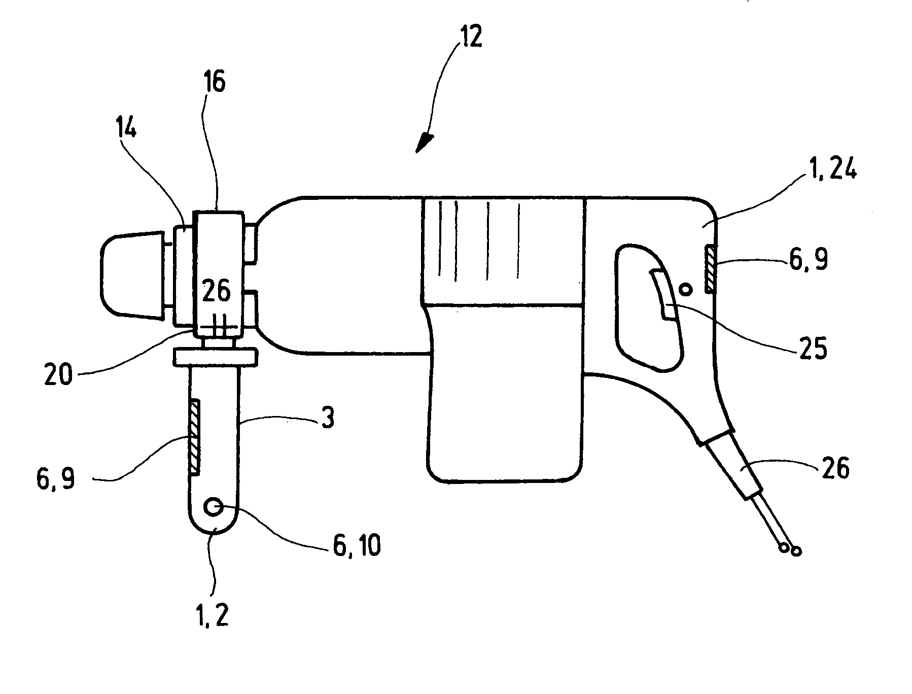
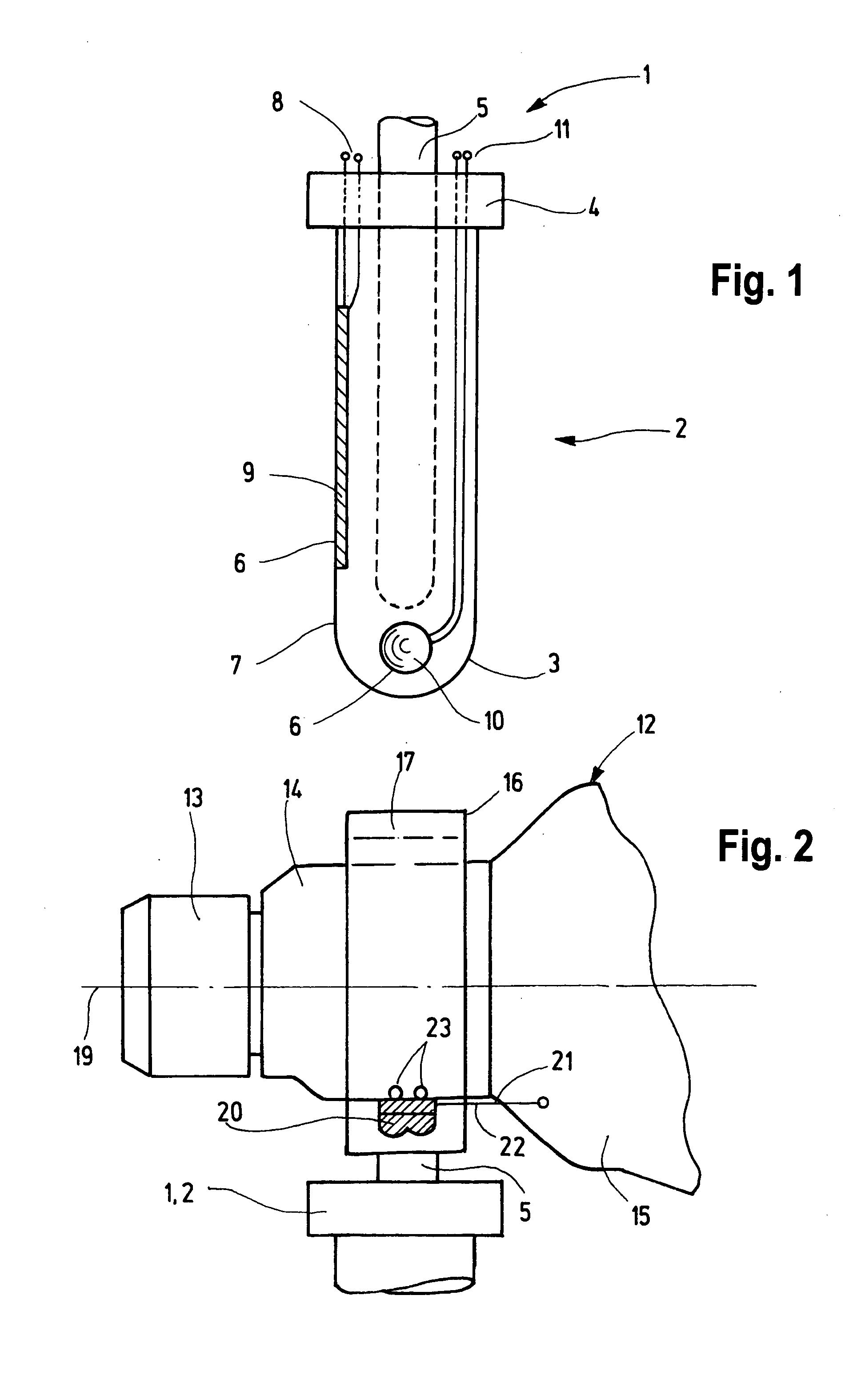
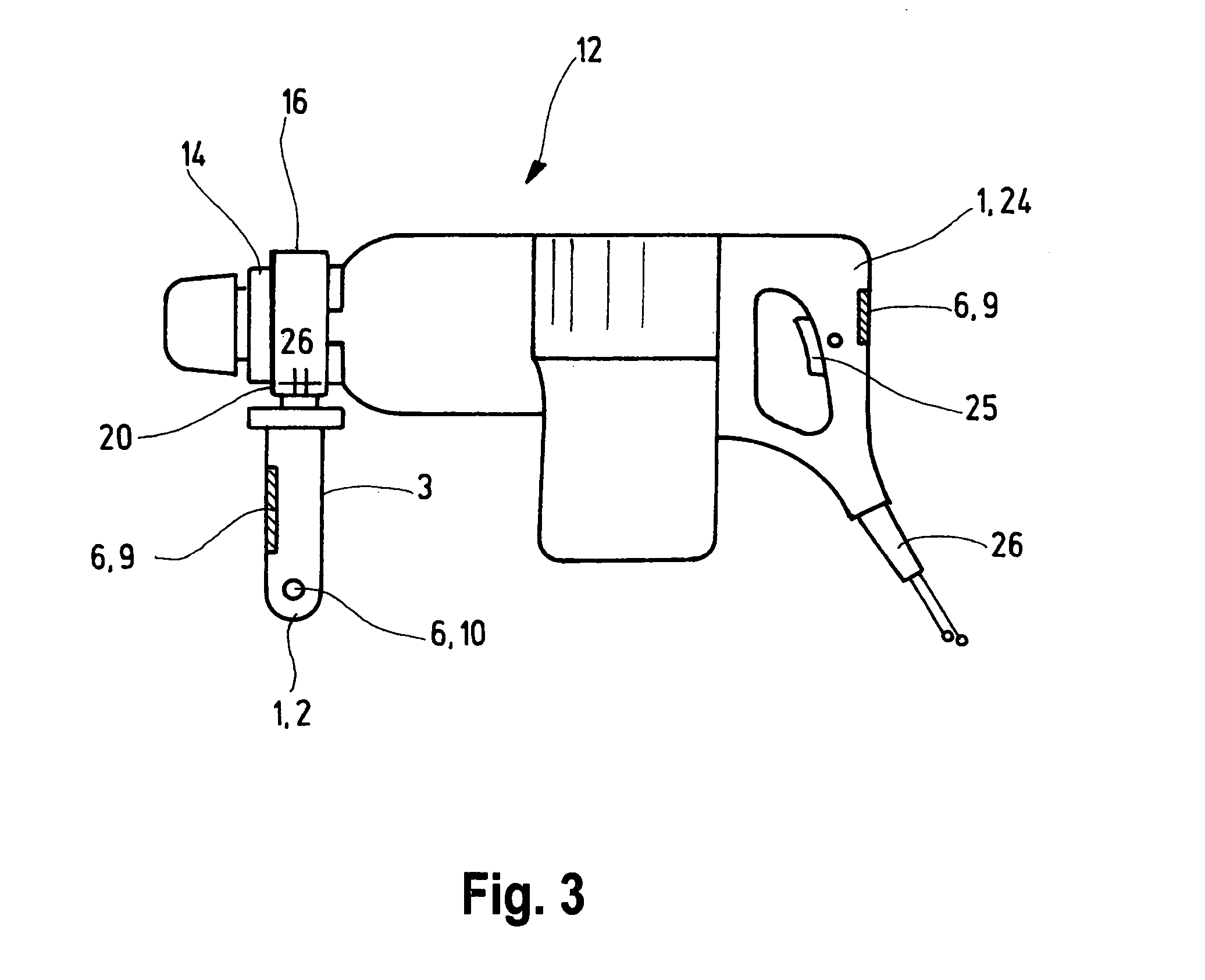
[0028]FIG. 1 shows a handle 1 that is embodied as an auxiliary handle 2. The handle has a grip 3 that is provided with a hand guard 4. Essentially in the center inside the grip 3, there is a dimensionally stable, essentially rod-shaped support 5; its extension above the hand guard 4 is not shown, thus giving only a partial view of the support 5. This support 5 serves to attach the handle 1 to an electric tool, not shown, and in particular, to transmit force between the grip 3 and the electric tool, not shown. In its grip 3, the handle 1 has a detecting unit 6. This detecting unit is essentially provided over a certain portion of the surface 7 of the grip 3. The span over the surface 7 of the grip 3 must extend far enough to permit an unambiguous detection as to whether the handle is being grasped firmly or only touched loosely. The precise location of the detecting unit 6 on the surface 7 of the grip 3 is unimportant, as long as this function is reliably fulfilled.

[0029] In this ex...


PUM

PropertyMeasurementUnit
torqueaaaaaaaaaa
diametersaaaaaaaaaa
forcesaaaaaaaaaa

Abstract

The invention relates to a handle for an electric tool. The handle according to the invention has at least one detecting unit.

Description

[0001] The invention relates to a handle for an electric tool. BACKGROUND OF THE INVENTION [0002] Electric tools are provided with handles for operating them. Drills or pneumatic drills, for example, are provided with a handle that permits the electric tool to be held in the working position. This handle is frequently associated with an on-off switch and / or other controls. In the broadest sense, therefore, the handle is used to operate the electric tool. It permits the electric tool to be held in the working position, a force to be exerted, in particular along the central axis of the device and therefore parallel to the axis of a tool being used, for example a drill bit, and a torque to be exerted, which is used as a reaction torque opposing the torque resulting from the rotation of the tool when a load is placed on it. [0003] In addition, auxiliary handles are known, which permit a two-handed operation of an electric tool. The main handle, which is usually situated at the end of th...

Claims


Application Information

Patent Timeline
Patent Type & Authority Applications(United States)
IPC IPC(8): B25F5/00B25F5/02
CPCB25F5/026B25F5/00B23B25/06B23B45/001B23B45/003B25D17/00
Inventor FRAUHAMMER, KARLMEIXNER, GERHARDKUHNLE, AXELSTRASSER, ANDREASHOFFMANN, ERHARDHAHN, DIETMARHEILMANN, ANDREASSINGLE, ULRICH
Owner ROBERT BOSCH GMBH
Why Eureka
Try Eureka