Mirror mount assembly with dual reflective surfaces

a mirror mount and mirror technology, applied in the direction of machine supports, other domestic objects, transportation and packaging, etc., can solve the problems of 25 schoolchildren being killed, and the blind spot behind the combination mirror is larger than the one behind i

Inactive Publication Date: 2005-07-28
SCHMIDT WILLIAM P +2
View PDF2 Cites 17 Cited by
  • Summary
  • Abstract
  • Description
  • Claims
  • Application Information

AI Technical Summary

Benefits of technology

[0022] When positioned at the extreme front end on a Type C school bus, one of the reflective surfaces provides an expanded field-of-view below and alongside the driver and a second...

Problems solved by technology

However, the National School Transportation Association reports that 25 school children were killed in school bus loading zones in the 1995-96 school year.
In one conventional bus mirror system, the driver often has four convex mirrors disposed on the front of the bus (see FIG. 1A), creating numerous blindspots, the need for independent mirror mounts, and confusion as to which mirror he or she should view in various situations.
In a second conventional bus mirro...

Method used


Image

  • Mirror mount assembly with dual reflective surfaces
  • Mirror mount assembly with dual reflective surfaces
  • Mirror mount assembly with dual reflective surfaces

Examples


Embodiment Construction

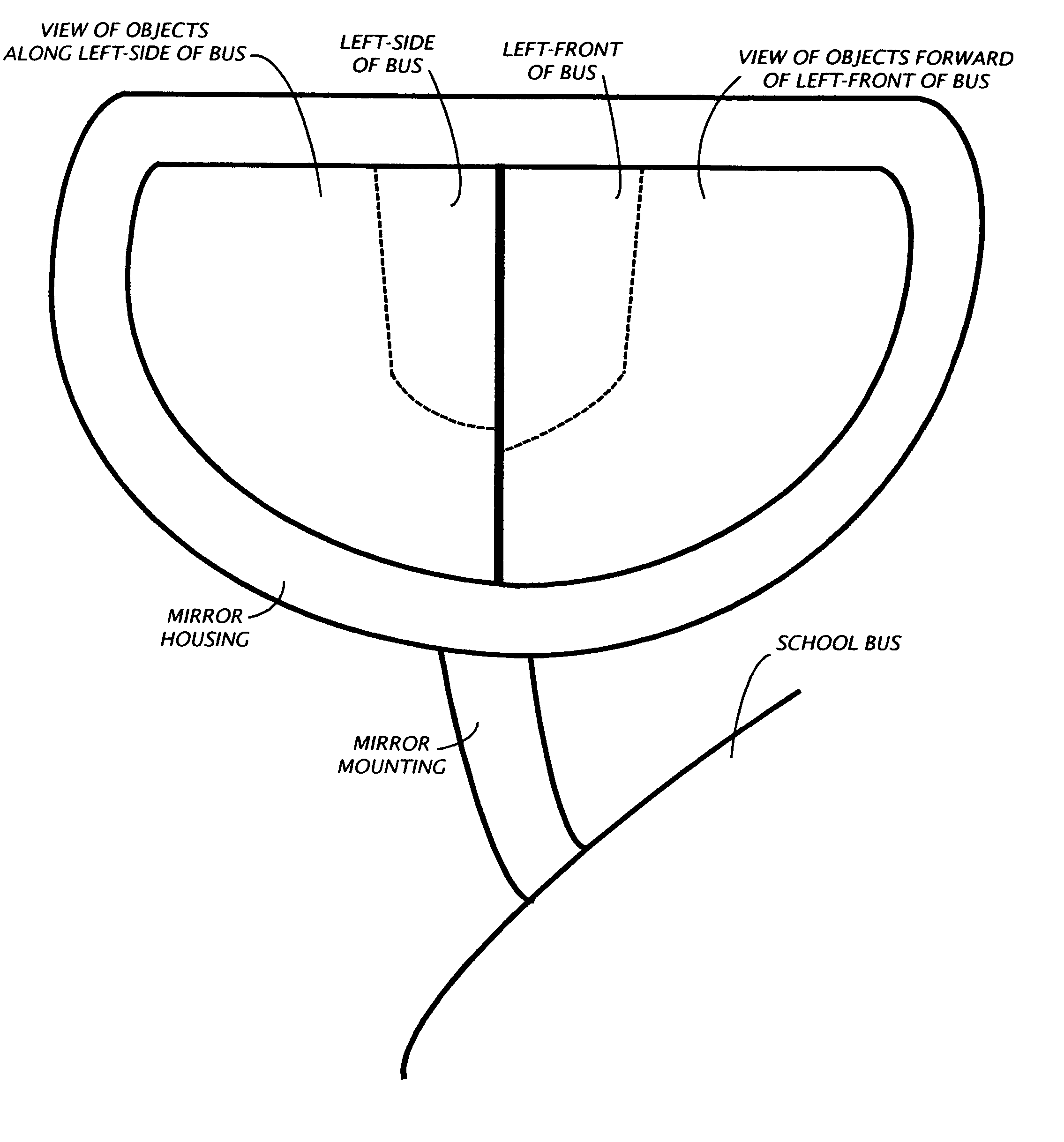
[0036] Referring now to the drawings with initial reference to FIGS. 1C and 2 which illustrate an environmental view of the preferred embodiment of the mirror mount assembly 10 of the present invention—a dual mirror mount assembly mounted onto a Type C school bus 12.

[0037] The mirror mount assembly 10 as shown comprises a mirror housing 20, and a pair of reflective surfaces (30 and 40) secured within the mirror housing 20. The front reflective surface 30 has a substantially convex shape. The front reflective surface 30 is primarily configured so that when the mirror mount assembly 10 is properly positioned, the front reflective surface 30 provides the school bus driver with an expanded field-of-view of objects disposed in a first zone. The side reflective surface 40 is separate and distinct from the front reflective surface 30 (alongside and below the school bus driver. The side reflective surface 40 also has a substantially convex shape. The side reflective surface 40 is primarily...


PUM


Abstract

A mirror mount assembly includes multiple reflective surfaces disposed within a mirror housing for use on a vehicle. The reflective surfaces of each reflective surface are designed and configured for mounting at a pre-selected site. When so mounted, each reflective surface provides an expanded field-of-view of objects disposed in a specific zone proximate to the mirror mount assembly. When positioned at the extreme front end of the hood of a Type-C school bus, one of the reflective surfaces provides an expanded field-of-view below and alongside the driver and a reflective surface provides an expanded field-of-view below and in front of the school bus. On a Type-D school bus, the mirror mount assembly is disposed above the driver and suspended from the roof of the bus—the housing inkling the two reflective surfaces and a rear-view mirror. The reflective surfaces are designed to provide the driver with the best images in the target zones while minimizing the blindspot behind the mirror mount assembly. Either reflective surface may be adjustable within the housing to account for differing size and shapes of vehicle drivers.

Description

TECHNICAL FIELD [0001] The present invention relates to a mirror mount assembly for mounting onto large commercial vehicles, recreational vehicles, and buses, including but not limited to trucks, school buses, buses for public transportation, trailers, garbage trucks, boats, cars, station wagons, trains, aircraft, and boats, and more particularly, to a mirror mounting assembly including multiple reflective surfaces. BACKGROUND OF THE INVENTION [0002] While the technology set forth herein has broad applications to large commercial vehicles, recreational vehicles, and buses, for purposes of example and illustration this technology is shown in this specification in school bus applications. One skilled in the art can readily apply such teachings to such other vehicles. [0003] School buses are the single largest system of public transportation in the U.S., providing about 10 billion rides annually to students grades K through 12. Each year, roughly 440,000 public school buses travel 4.3 ...

Claims


Application Information

Patent Timeline
IPC IPC(8): B60R1/00B60R1/08
CPCB60R1/006B60R1/082B60R1/007
Inventor SCHMIDT, WILLIAM P.SCHMIDT, WILLIAM P. JR.SWAIN, DANIEL M.
Owner SCHMIDT WILLIAM P
Why Eureka
Try Eureka