Antenna for reader/writer and reader/writer having the antenna

a technology for reading/writing and antennas, applied in the direction of near-field systems using receivers, instruments, sensing by electromagnetic radiation, etc., can solve the problems of increased loss, difficult handling point of view, and increased loss

Inactive Publication Date: 2005-07-28
MITSUBISHI MATERIALS CORP
View PDF9 Cites 133 Cited by
  • Summary
  • Abstract
  • Description
  • Claims
  • Application Information

AI Technical Summary

Benefits of technology

[0007] The present invention was made in consideration of the above problems. A main object of the present invention is to provide an RFID antenna. In particular, a main object of the present invention is to provide a reader / writer antenna which can restrict a variance of the resonating frequency and a loss even if the RFID antenna or the reader / writer antenna are disposed so as to contact a conductive member such as a metal casing.
[0018] By doing this, in the present invention, a soft magnetic member which is made of a soft magnetic member which is formed by a layered member such as a composite which is formed by combining a metal powder member, a flake, or a ferrite and an organic member, a ferrite, an amorphous film or a layered member of amorphous film is disposed between the antenna coil for the reader / writer antenna and the conductive member such as a metal casing. By doing this, it is possible to transmit the magnetic flux which is generated by the antenna coil through the soft magnetic member; thus, it is possible to restrict the variance for the resonating frequency which is generated by an eddy current which is generated in the metal member and the loss. In particular, by using a composite which is formed by controlling a disposition direction of the flake, it is possible to form a thin soft magnetic member; thus, it is possible to dispose an antenna coil on a metal flat plate such as a casing.
[0019] Also, by inserting a conductive member which has a predetermined electric resistance between the soft magnetic member and a surface of the metal member, it is possible to restrict an inductance which is caused by a variety of a material member of the conductive member to which the antenna is disposed and a variance for the loss. Thus, it is always possible to obtain a stable antenna performance even in a case in which an antenna coil is disposed in any kinds of place.

Problems solved by technology

By doing this, an eddy current is generated in the metal member; thus, there are problems in that a resonation frequency in a resonating circuit which is formed by an antenna coil and a condenser varies, or a loss increases.
These electronic circuits and a supporting member for supporting such circuits contain a lot of metal member; therefore, in the reader / writer antenna, there occur a variance for the resonating frequency and a loss may increase due to receiving an influence of these metal members.
Such a condition is not easy for a handling point of view.
However, if the hollow coil antenna is disposed so as to contact the casing, the variance for the resonating frequency and the loss may increase greatly.
Also, if the case if made from a plastic member and there is a disposition layer such as an aluminum, or a metal member such as an aluminum flake is contained in a filling member or a painting layer, there may be a case in which a loss in the coil may increase greatly.

Method used


Image

  • Antenna for reader/writer and reader/writer having the antenna
  • Antenna for reader/writer and reader/writer having the antenna
  • Antenna for reader/writer and reader/writer having the antenna

Examples


embodiment 1

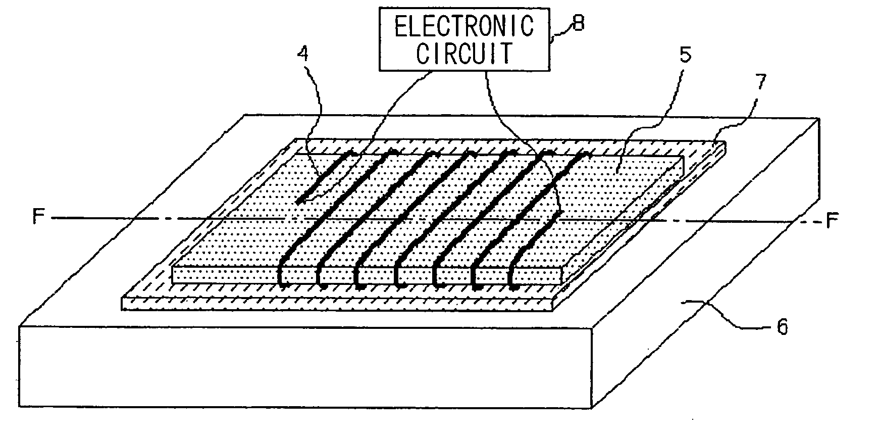
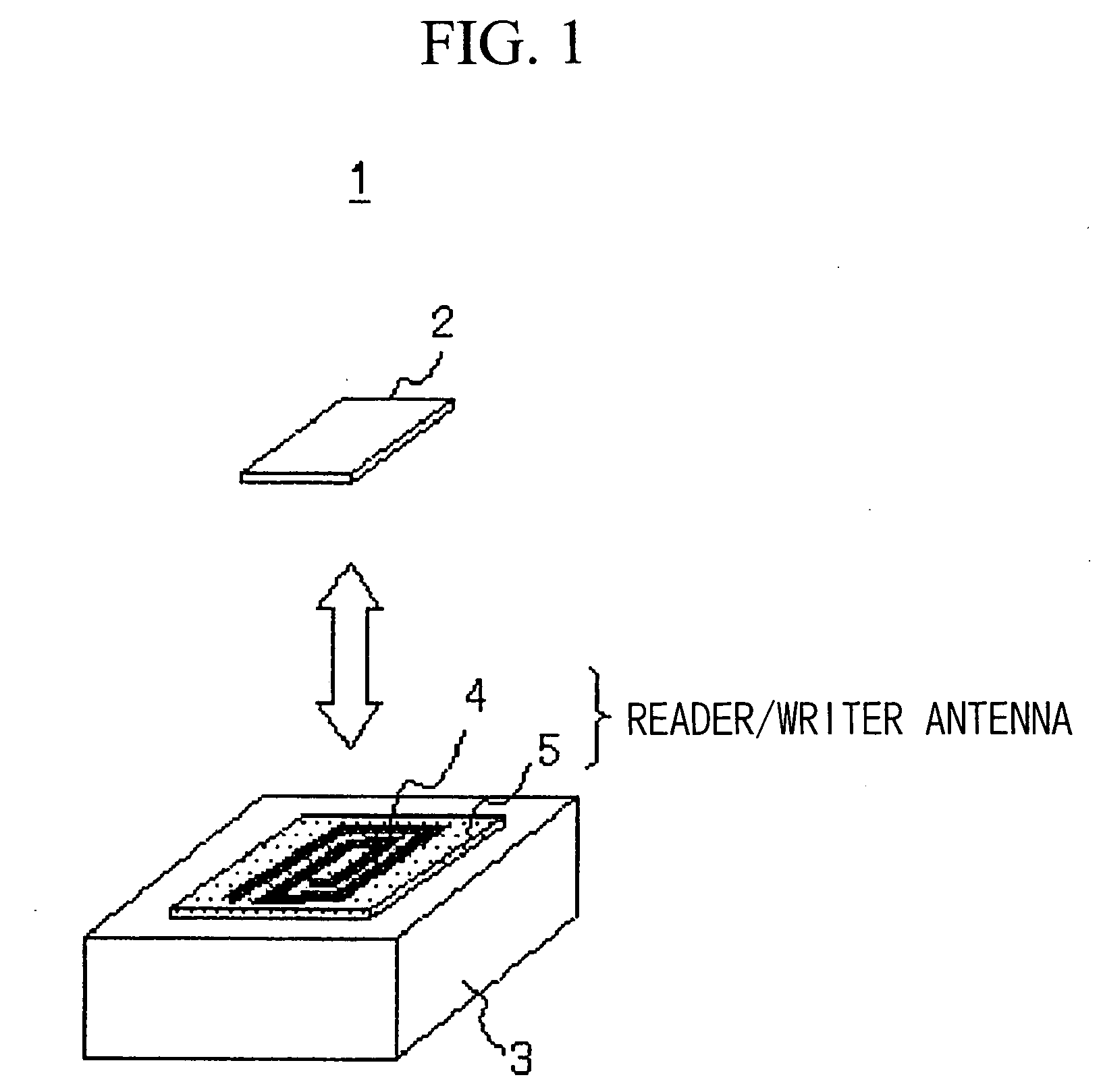
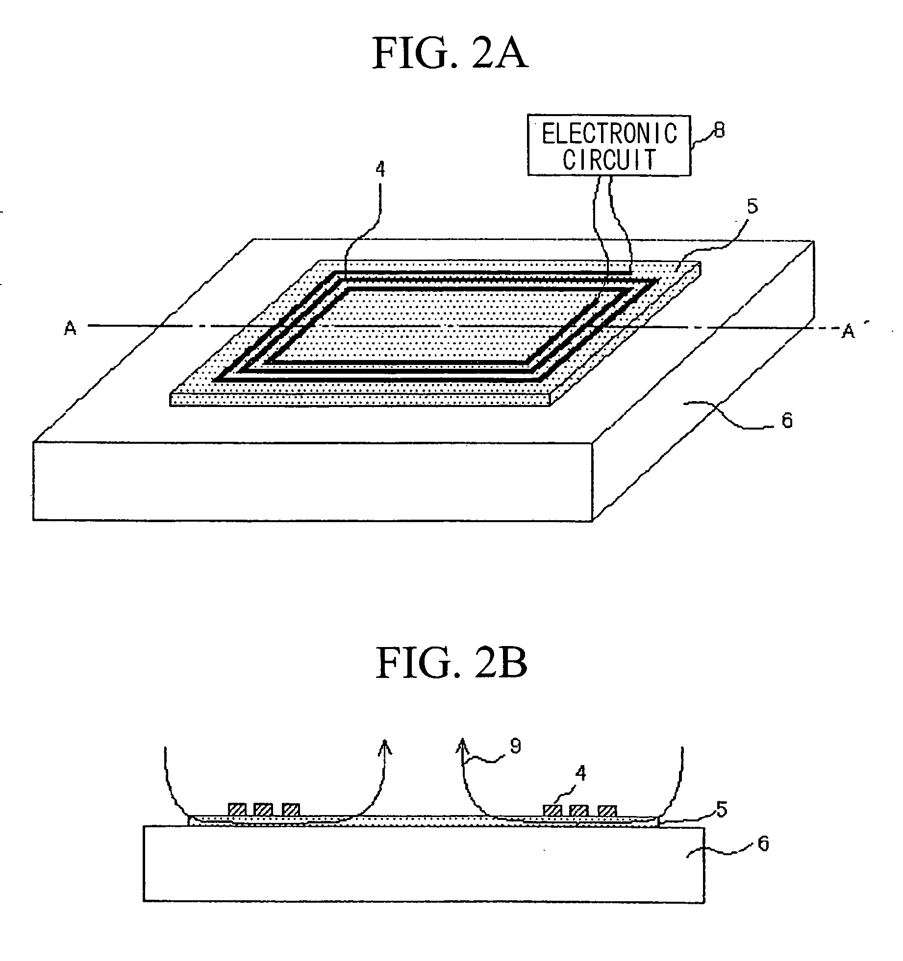
[0043] First, a reader / writer antenna according to a first embodiment of the present invention is explained with reference to FIGS. 1A to 6B. FIG. 1 is a view for showing a structure of an RFID system of the present invention. FIGS. 2A to 3B are views for showing structures for the reader / writer antennas according to the first embodiment. FIGS. 2A and 3A are isometric views. FIGS. 2B and 3B are cross sections for them. Also, FIGS. 4A and 4B are cross sections for showing a structure for a soft magnetic member which is used for the reader / writer antenna according to the present embodiment. FIGS. 5A and 5B are views for showing other structure of the reader / writer antenna according to the present embodiment.

[0044] AS shown in FIG. 1, the RFID system 1 is formed by a reader / writer 3 (or a reader, hereinafter called a reader / writer) for performing a datum communication by using the reader / writer antenna and a transponder 2 which has various shapes such as a label type, sheet type, or s...

second embodiment

[0075] Next, a reader / writer antenna according to a second embodiment of the present invention is explained with reference to FIGS. 7A to 8B. FIGS. 7A to 8B are views for showing a structure for a reader / writer antenna according to the second embodiment of the present invention. Here, the present embodiment is characterized in that the soft magnetic member is disposed in a part between the antenna coil and the metal surface; thus, the structure, the material member, and the manufacturing method therefore are the same as those in the above explained first embodiment.

[0076] As shown in FIGS. 7A and 7B, in the reader / writer antenna according to the present embodiment, a soft magnetic member 5 which is formed by the material member and the manufacturing method which are shown in the first embodiment is disposed in a part between the antenna coil 4 and the metal surface 6, and a spacer 14 for adjusting the thickness is disposed in other sections. In such a structure, a symmetry of the m...

third embodiment

[0081] Next, the reader / writer antenna according to the third embodiment of the present invention is explained with reference to FIGS. 9A to 11B. FIGS. 9A to 10B are views for showing a structure for the reader / writer antenna according to the third embodiment of the present invention. FIGS. 11A and 11B are views for showing a position for disposing the reader / writer antenna. Here, the present embodiment is characterized in that the antenna coil is wound around the soft magnetic member. The rest of the features such as a structure, material members, and manufacturing method are the same as those explained in the first and the second embodiments.

[0082] As shown in FIG. 9, a flat soft magnetic member 5 is disposed approximately in parallel with the metal surface 6 in the reader / writer antenna according to the present embodiment and the antenna coil 4 is wound around the soft magnetic member 5 as a magnetic core. In such a structure, a protruding amount of the antenna coil is large bec...


PUM

PropertyMeasurementUnit
thicknessaaaaaaaaaa
lengthaaaaaaaaaa
resistanceaaaaaaaaaa

Abstract

A soft magnetic member (5) which is formed by a composite of an organic object such as a metal grain powder, a flake, a ferrite grain powder, a ferrite, an amorphous film or a layered member of the amorphous film with 10 mm or lower thickness so as to satisfy a predetermined relationship with an antenna area, a circumference length, and a magnetic transmission ratio and a conductive member (7) which has approximately 10×10−8 Ωm or lower, more preferably 0.005 Ω or lower initial resistance are provided between the an antenna coil which is formed at least one loop and a metal surface (6) of the conductive member such as a metal casing. The magnetic flux which invades into the conductive object is blocked by the soft magnetic member (5) and the conductive member (7) so as to restrict the influence thereof. By doing this, it is possible to provide a reader / writer antenna for an RFID system in which it is possible to restrict a variance of a resonating frequency and an increase in a loss even if it is disposed so as to contact the conductive object such as a metal casing.

Description

TECHNICAL FIELD [0001] The present invention relates to a structure for an antenna for an RFID (Radio Frequency Identification) system in which data are read / written in a non-contacting manner for a mounted IC chip. In particular, the present invention relates to a structure for a reader / writer antenna which can be used so as to contact to a metal member. BACKGROUND ART [0002] In recent years, an RFID system is commonly used in which data are transmitted between a transponder which is provided with an IC chip and a reader / writer (or a reader). In such an RFID system, data are transmitted by using antennae which are provided to the transponder and the reader / writer. Therefore, it is possible to perform data communication even if the transponder is disposed from the reader / writer by several centimeters to several tens centimeters. Also, there is an advantage to a dirty condition or a static electricity; thus, such an RFID system is commonly used for various usages such as a production...

Claims


Application Information

Patent Timeline
Patent Type & Authority Applications(United States)
IPC IPC(8): G06K7/08G06K17/00G06K7/10H01Q1/22H01Q1/52H01Q7/06H04B1/59H04B5/02
CPCG06K7/10336G06K7/10346G06K19/07771H01Q7/06H01Q1/2216H01Q1/52H01Q1/22
Inventor ENDO, TAKANORIYAHATA, SEIROUTSUCHIDA, TAKASHI
Owner MITSUBISHI MATERIALS CORP
Why Eureka
Try Eureka