Apparatus with one or more capacitive touchpads as interface

a technology of capacitive touchpads and apparatuses, applied in the field of peripheral apparatuses of computer systems, can solve problems such as limiting applications, introducing errors in generated signals, and metal switches within encoders deteriorating,

Inactive Publication Date: 2005-07-28
ELAN MICROELECTRONICS CORPORATION
View PDF4 Cites 23 Cited by
  • Summary
  • Abstract
  • Description
  • Claims
  • Application Information

AI Technical Summary

Benefits of technology

[0017] According to the present invention, an apparatus comprises one or more capacitive touchpads mounted on a case as input interface, and a microprocessor within the case connected to the capacitive touchpads. Each of the capacitive touchpads generates a signal representative of capacitance change in response to a touch thereon, and the microprocessor determines the displacement, moving speed, relative position, or continuing and discontinuing time of the touch from the signal representative of capacitance change, to accordingly generate corresponding output as a button, Z-axis or scrolling signal. The Z-axis and scrolling signals could provide the control of scrolling on a window or acceleration of scrolling on a window.

Problems solved by technology

After the mouse is used for a time period, however, a mechanical Z-axis mechanism will have abnormal scrolling of the wheel due to the wear out of the wheel and its axis, and the metal switch within the encoder will deteriorate with poor contacting and bouncing, which will introduce errors in the generated signals.
In addition, the wheel mechanism occupies large space that is disadvantageous to the mechanism design of a mouse, and thus restricts the applications.
Furthermore, a wheel mechanism provides only one direction of Z-axis scrolling, and therefore, a second wheel mechanism is required if another direction of Z-axis scrolling is desired, thereby increasing the occupied space and manufacturing cost.
If the wheel is not precisely positioned, jitters will be occurred in the signals generated by the receiver, and errors are easily introduced in the signals.
In addition, the optical emitter and receiver have to be continuously lighted up and thus consume huge electric power.
An optical wheel mechanism also occupies large space and thus limits the mechanism design of the mouse and the applications.
Likewise, a wheel mechanism provides only one direction of Z-axis scrolling, and therefore, a second wheel mechanism is required if another direction of Z-axis scrolling is desired, thereby increasing the occupied space and manufacturing cost.
Due to the similar structure and operational principles, it is disadvantageous as a digital one.
Moreover, the buttons and the wheel mechanism of a conventional mouse require the user to apply more force by his fingers for operations, and long-time usage may cause the fingers fatigue, even damaged.
Particularly, in the applications of the small mouse for kids, the conventional wheel mechanism is disadvantageous to scale down for a mouse, and the pressing force needed to be applied on the buttons and wheel mechanism are disadvantageous for kids to operate the mouse.
In order to reduce the force needed to press the button, a large button mechanism is necessary for a mouse to provide longer force arm, and it is again disadvantageous to scale down for a mouse.
The structure and operational principles of this scrolling apparatus is also similar to that of the wheel mechanism in the aforementioned mouse, it is thus disadvantageous hereto for the same reasons.
Although several arts have been proposed for improvement to the Z-axis and scrolling apparatus in conventional mice and keyboards, their mechanisms and operational principles are still within the scope of the aforementioned ones, and thus the drawbacks could not be removed.

Method used


Image

  • Apparatus with one or more capacitive touchpads as interface
  • Apparatus with one or more capacitive touchpads as interface
  • Apparatus with one or more capacitive touchpads as interface

Examples


first embodiment

[0028]FIG. 3 shows a schematic diagram of the first embodiment for a mouse according to the present invention. On a case 21 of a mouse 20, capacitive touchpad 26 extending in the vertical direction and capacitive touchpad 28 extending in the horizontal direction to serve as ZY-axis and ZX-axis 28 are mounted between a left button 22 and a right button 24. In other embodiments, the Z-axis mechanisms 26 and 28 may be mounted on the case 21 at other positions. The left button 22 and right button 24 have the same function as a typical mouse, and button switch mechanism is employed for them both. In a preferred embodiment, the ZY-axis 26 is provided for the control of scrolling on a window in the vertical direction, and the ZX-axis 28 is provided for the control of scrolling on the window in the horizontal direction. Uniform profile or saw structure 23 with equally spaced teeth are formed on the surfaces of the ZY-axis 26 and ZX-axis 28 to enhance the touch feel when user's fingers move ...

second embodiment

[0029]FIG. 4 shows a schematic diagram of the second embodiment for a mouse according to the present invention. On the case 31 of a mouse 30, there are three independent capacitive touchpads 32, 33 and 34 mounted thereon for a left button, middle button and right button, respectively. In other embodiments, one capacitive touchpad is defined three or more regions thereon, each of them served as a key. In a preferred embodiment, one click on any of the buttons 32, 33 and 34 is determined by the continuing and discontinuing time of a touch thereon. For example, if the time interval between two touches on the button 32 or 34 falls in a predetermined range, it is determined to be a single click of the corresponding button, and a quick double touches on the button 33 is determined to be a single click of the button 33. The middle button 33 may be used to define a function key or a hot key.

third embodiment

[0030]FIG. 5 shows a schematic diagram of the third embodiment for a mouse according to the present invention. A single capacitive touchpad 49 is mounted on the case 41 of a mouse 40, and has several patterns printed thereon to indicate a left button area 42, a right button area 44, and ZY-axis area 46 and ZX-axis area 48 therebetween. A small protruding saw 43 is printed on the ZY-axis area 46 and ZX-axis area 48 to enhance the touch feel and for easy control of movement. The function and operation of the left button area 42 and right button area 44 are the same as the left button 32 and right button 34 of the mouse 30 shown in FIG. 4. The ZY-axis area 46 extends in the vertical direction, and the ZX-axis area 48 extends in the horizontal direction, whose function and operation are the same as the ZY-axis 26 and ZX-axis 28 of the mouse 20 shown in FIG. 3.

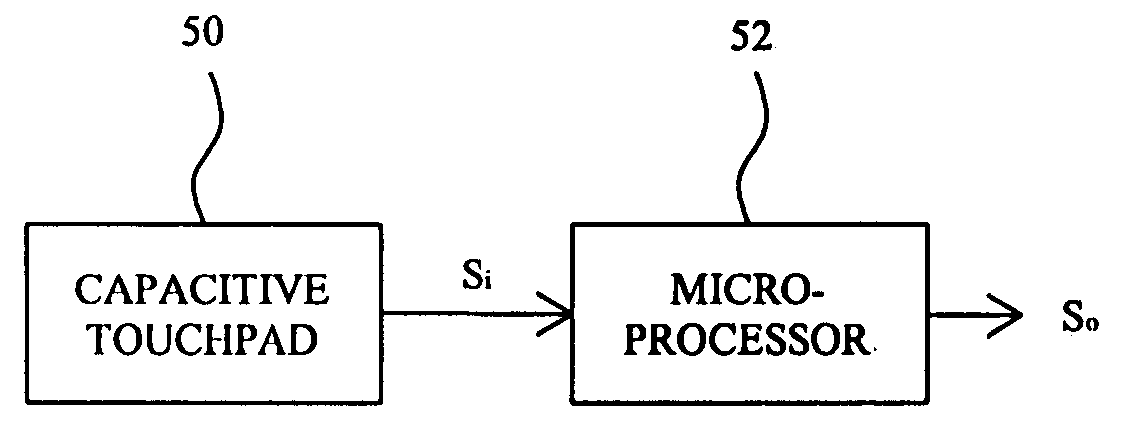
[0031]FIG. 6 shows a functional block diagram for the various embodiments shown in FIGS. 3-5, which is used to execute the operat...


PUM


Abstract

An apparatus comprises a case, one or more capacitive touchpads mounted on the case for serving as the input interface of the apparatus, and a microprocessor within the case connected to the capacitive touchpads. Each of the capacitive pads generates a signal representative of capacitance change in response to a touch thereon, and the microprocessor determines the displacement, moving speed, relative position, or continuing and discontinuing time of the touch from the signal representative of capacitance change, to accordingly generate corresponding output as a button, Z-axis or scrolling signal.

Description

FIELD OF THE INVENTION [0001] The present invention is related generally to a peripheral apparatus of a computer system, and more particularly, to an apparatus with one or more capacitive touchpads as interface of the apparatus. BACKGROUND OF THE INVENTION [0002] Peripheral apparatus are important equipments for a computer system, which are used to implement the input / output (I / O) functions or to expend the functions of a computer system. In particular, keyboard and mouse have become fundamental peripheral apparatus of a computer system. As a human-machine interface, keyboard and mouse have been improved continuously, to have smaller volume, lighter weight, and lower cost to provide users more functions and higher efficiency. [0003] A conventional mouse has two, three or more buttons to generate button signals in response to the clicks thereon for supplying to the system host. An improved mouse additionally has Z-axis mechanism using a wheel to generate Z-axis signal in response to ...

Claims


Application Information

Patent Timeline
Patent Type & Authority Applications(United States)
IPC IPC(8): G06F3/033G06F3/044G09G5/00
CPCG06F3/03543G06F3/044G06F3/03547G06F3/0446
Inventor CHIU, YEN-CHANGCHIEN, YUNG-LIEHTANG, CHENG-HAO
Owner ELAN MICROELECTRONICS CORPORATION
Why Eureka
Try Eureka