Image forming apparatus

a technology of forming apparatus and nozzles, which is applied in the direction of printing, other printing apparatus, etc., can solve the problems of reducing the quality of recorded images, ink blockages, and ejection errors of parts of the plurality of nozzles, and achieve the effect of saving spa

Inactive Publication Date: 2005-07-28
FUJIFILM CORP
View PDF4 Cites 37 Cited by
  • Summary
  • Abstract
  • Description
  • Claims
  • Application Information

AI Technical Summary

Benefits of technology

[0030] According to the present invention, restoration processes, such as nozzle flushing (preliminary ejection), wiping, nozzle suctioning, or the like, and nozzle drying prevention processes, such as capping, can be performed while maintaining the rigidity of a medium supporting section (conveyance belt), and while also contributing toward space savings by compactification of the apparatus.

Problems solved by technology

A portion of the plurality of nozzles may generate ejection errors, such as ink blockages, or defects in the amount of ink ejected (the dot size deposited on the recording paper) or the direction of flight of the ink (the position at which the ink is deposited), due to drying of the ink, adherence of foreign material, or the like.
Nozzles suffering from ejection errors of this kind cause a decline in the quality of the recorded image, and therefore processing for restoring the recording head is carried out as necessary.
Therefore, a problem arises in that the rigidity of the conveyance belt is reduced by the presence of a large opening section.
A further problem arises in that preliminary ejection can only be carried out in the specific open region of the belt, and hence productivity declines.
However, a problem arises in that it is not possible to carry out wiping or nozzle suctioning.
Moreover, since the recording paper is conveyed by simply being placed on a conveyance belt, a further problem arises in that the recording paper cannot be conveyed stably.

Method used


Image

  • Image forming apparatus
  • Image forming apparatus
  • Image forming apparatus

Examples


first embodiment

[0040] Below, an image forming apparatus according to the present invention is described with reference to the accompanying drawings.

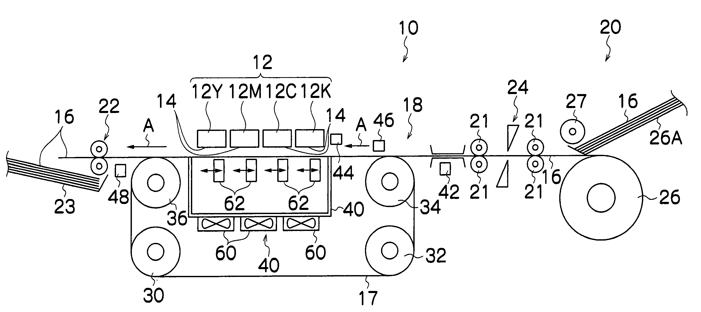
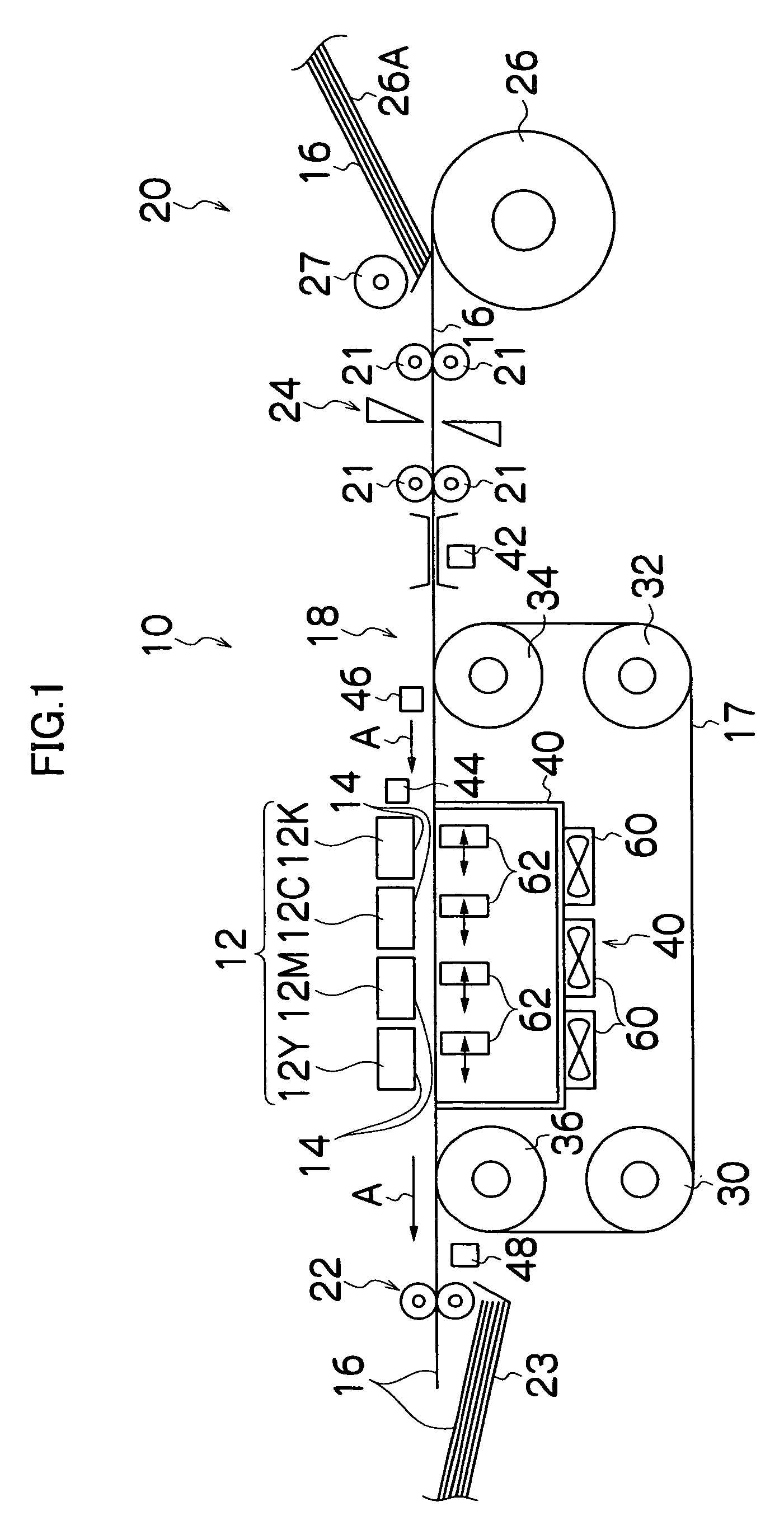
[0041]FIG. 1 is a diagram of the general composition of an inkjet type image forming apparatus according to an embodiment of the present invention. This image forming apparatus 10 comprises: recording heads 12K, 12C, 12M, 12Y for ink colors of black (K), cyan (C), magenta (M) and yellow (Y) (referred to simply as “recording head 12” in some instances below); a belt conveyance unit 18, which is disposed facing the nozzle face 14 of the recording head 12, for conveying a recording paper 16 on a belt 17 while keeping the recording paper 16 flat; a paper supply unit 20 for supplying a recording paper 16; and a paper output unit 22 for outputting recording paper formed with an image to the exterior. Furthermore, a paper output tray 23, or the like, for stacking sheets of recording paper 16 formed with images is arranged in the paper output unit 22.

[0042] T...


PUM


Abstract

The image forming apparatus comprises: a line type recording head in which a plurality of nozzles ejecting ink are arranged through a length corresponding to a full width of a recording medium; a recording medium conveyance device which supports and conveys the recording medium in a direction of conveyance of the recording medium and causes the recording head and the recording medium to move relatively to each other, the recording medium conveyance device including a medium supporting part which supports the recording medium, a plurality of opening sections being formed in the medium supporting part, the plurality of opening sections being arranged in a staggered matrix in such a manner that at least one of the plurality of opening sections is present throughout a whole width of a nozzle region of the recording head when the plurality of opening sections are projected so as to be aligned in a direction substantially orthogonal to the direction of conveyance of the recording medium; an ejection control device which performs control of preliminary ejection of the ink from the recording head toward the opening sections in synchronism with positions of the opening sections; and an ink receiving member which receives the ink in the preliminarily ejection through the opening sections.

Description

BACKGROUND OF THE INVENTION [0001] 1. Field of the Invention [0002] The present invention relates to an image forming apparatus, and more particularly, to an image forming apparatus comprising a device which restores nozzles of a recording head. [0003] 2. Description of the Related Art [0004] An image forming apparatus such as an inkjet printer has a recording head comprising a plurality of nozzles and forms an image on recording paper by ejecting ink onto the recording paper from nozzles of the recording head. A portion of the plurality of nozzles may generate ejection errors, such as ink blockages, or defects in the amount of ink ejected (the dot size deposited on the recording paper) or the direction of flight of the ink (the position at which the ink is deposited), due to drying of the ink, adherence of foreign material, or the like. Nozzles suffering from ejection errors of this kind cause a decline in the quality of the recorded image, and therefore processing for restoring th...

Claims


Application Information

Patent Timeline
Patent Type & Authority Applications(United States)
IPC IPC(8): B41J2/165B41J29/377B41J29/38B41J29/393
CPCB41J2/16585B41J29/393B41J29/377
Inventor KACHI, YASUHIKO
Owner FUJIFILM CORP
Why Eureka
Try Eureka