Coordinate offset adjustment system and coordinate offset adjustment method

a technology of offset adjustment and coordinates, applied in the direction of electric programme control, program control, instruments, etc., can solve the problems of error detection of light, constant risk of damage to hard disk drive, and imposed capacity

Inactive Publication Date: 2005-07-28
NEC CORP
View PDF7 Cites 13 Cited by
  • Summary
  • Abstract
  • Description
  • Claims
  • Application Information

AI Technical Summary

Benefits of technology

[0011] An object of the present invention is therefore to provide a coordinate offset adjustment system and a coordinate offset adjustment method capable of adjusting a coordinate offset without an occurrence of the error due to diffused reflection or ambient light.
[0019] According to the present invention, detecting the reference point using the reference point detection probe enables the coordinate offset to be adjusted based on the moving distance.
[0020] According to the present invention, measurement error can be reduced.
[0022] According to the present invention, the need of dedicated probe for coordinate offset adjustment is eliminated, thereby to reduce cost, space, and the like.

Problems solved by technology

The hard disk drive is constantly at the risk of being damaged, and a given limitation is imposed on the capacity thereof.
However, there is the following problem with the above system.
As a result, the light receiving element 904 makes an error detection of the light in some cases.
Further, error detections have occurred due to diffused reflection or ambient light.

Method used


Image

  • Coordinate offset adjustment system and coordinate offset adjustment method
  • Coordinate offset adjustment system and coordinate offset adjustment method
  • Coordinate offset adjustment system and coordinate offset adjustment method

Examples


Embodiment Construction

[0037] A preferred embodiment of the present invention will be described below in detail with reference to the accompanying drawings.

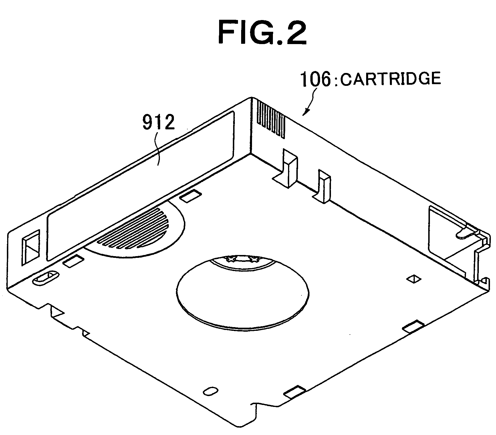
[0038]FIG. 3 is a perspective view showing a collective magnetic tape drive according to an embodiment of the present invention. The collective magnetic tape-drive includes a tape drive 101, two magazines 102 and an accessor mechanism 103. Each of the magazines 102 includes a plurality of cells 105 arranged two dimensionally in X and Y directions. A cartridge 106 is housed in each of the cell 105. The accessor mechanism 103 includes a picker mechanism 104. The main body of the accessor mechanism 103 is movable in X-direction. The picker mechanism 104 is movable in Y-direction and can be rotated about Y-axis.

[0039] In order to complete loading of the cartridge 106 that has been inserted into a certain cell into the tape drive 101, the following operation is performed. That is, the position of the accessor mechanism 103 in X-direction is firstly shifte...


PUM

PropertyMeasurementUnit
distanceaaaaaaaaaa
moving distancesaaaaaaaaaa
displacementaaaaaaaaaa

Abstract

According to an embodiment, a cartridge sensor shaft is allowed to butt against the vicinity of a positioning hole and is shifted toward the positioning hole. A coordinate offset error is then calculated based on a difference between the moving distance from the portion against which the cartridge sensor shaft butts to the portion at which the cartridge sensor shaft enters the positioning hole and the expected moving distance. The coordinate offset is adjusted by the calculated error. Further, in order to reduce measurement error, the cartridge sensor shaft is allowed to butt from both side of the positioning hole and shifted to detect the edges of the positioning hole, thereby calculating the coordinate offset error based on the two moving distances and two expected moving distances.

Description

BACKGROUND OF THE INVENTION [0001] 1. Field of the Invention: [0002] The present invention relates to a coordinate offset adjustment system and a coordinate offset adjustment method that adjust a coordinate offset, and more particularly to, a coordinate offset system and method that adjust an offset of the stop position of a picker mechanism in a collective magnetic tape drive. [0003] 2. Description of the Related Art: [0004] Programs and data used in a computer are, in general, stored in a hard disk drive and transferred, as needed, from the hard disk drive to a main memory at execution time of the program. The hard disk drive is constantly at the risk of being damaged, and a given limitation is imposed on the capacity thereof. Therefore, a backup apparatus that can store a large volume of programs and data with high reliability is required, even if the backup device operates at a low speed. As the backup apparatus, a magneto-optical disk drive, a DVD drive, a tape drive, and the l...

Claims


Application Information

Patent Timeline
Patent Type & Authority Applications(United States)
IPC IPC(8): G11B15/68G01B11/14G03F9/00G05B19/18G05B19/19G11B15/18G11B15/675G11B17/00G11B17/04G11B17/08G11B19/02G11B23/107G11B23/12
CPCG05B19/19G05B2219/49113G11B23/107G11B15/68G11B15/675
Inventor KAWASAKI, TOSHIMITSU
Owner NEC CORP
Why Eureka
Try Eureka