

Method and apparatus for characterizing coal tar in soil
a technology of coal tar and soil, applied in the field of methods and apparatus for characterizing coal tar in soil, can solve problems such as potential environmental problems, and no method or system that would provide one of skill in art with a way
- Summary
- Abstract
- Description
- Claims
- Application Information
AI Technical Summary
Benefits of technology
Problems solved by technology
Method used
Image

Examples
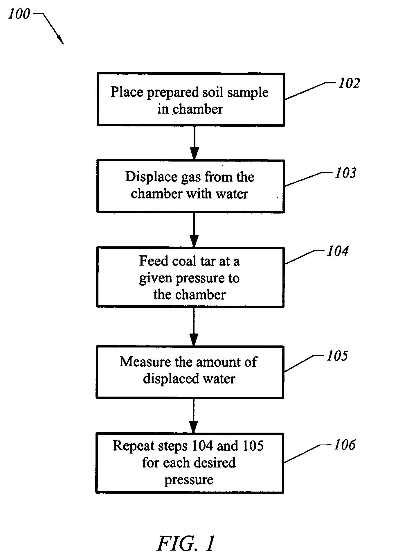
example 1
[0061] In order to determine the concentration of components in coal tar, extraction of MAHs and PAHs from coal tar samples from 9 MGP sites was performed using EPA method 3580 and analyzed by GC / MS with EPA method 8270, each of which are incorporated by reference herein in their entirety. Large particles of gravel, wood, and brick were removed, and the samples were homogenized by mixing in a stainless steel bowl. The concentrations of coal tar components are shown in Table 1.
TABLE 1Concentrations at Particular Sites (mg / kg)Compounds123456789Benzene4898449151452396498616901360Toluene21036902020310010003330284063704270Ethylbenzene4829201330901251647176025903790m / p-Zylenes28431201720292011603020210046203400Styrene1839541222450467508111034103370-Xylene1481610728160044016201060218015901,2,4Trimethylbenzene323195088418307052650113027102410Naphthalene100003270077702060027500288001390056100682002-Methylnaphthalene466019000527012300686027000862024000383001-Methylnaphthalene287016200333089...
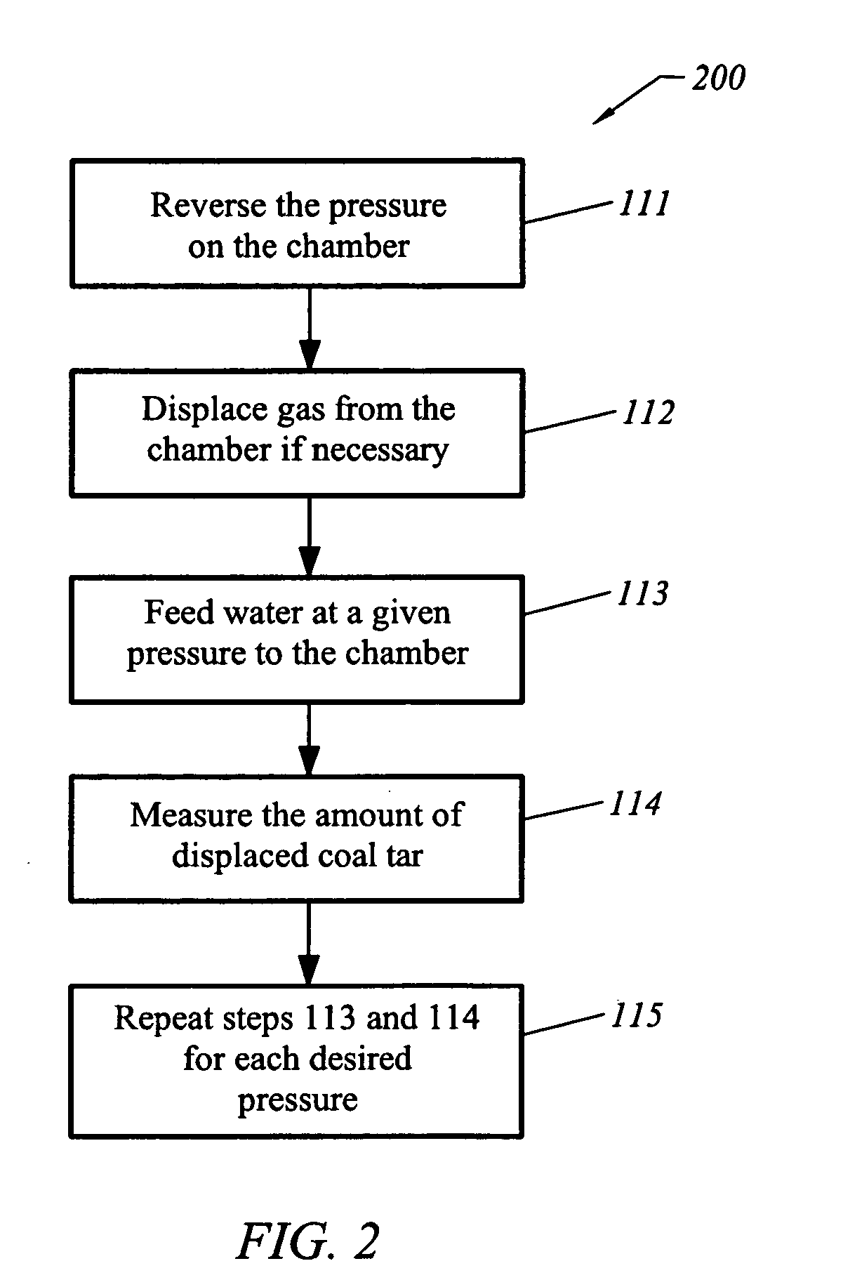
example 2
[0063]FIG. 6 is an example of a coal tar injection curve. It illustrates the drainage of water and the imbibition of coal tar. In this case the residual saturation of coal tar is approximately at 18% and 5000 mm Hg.
[0064] While the foregoing description and drawings represent the preferred embodiments of the present invention, it will be understood that various additions, modifications and substitutions may be made therein without departing from the spirit and scope of the present invention as defined in the accompanying claims. In particular, it will be clear to those skilled in the art that the present invention may be embodied in other specific forms, structures, arrangements, proportions, and with other elements, materials, and components, without departing from the spirit or essential characteristics thereof. The presently disclosed embodiments are, therefore, to be considered in all respects as illustrative and not restrictive, the scope of the invention being indicated by th...
PUM
 Abstract
Description
Claims
Application Information