
Head and neck protection system

a head and neck protection and head and neck technology, applied in the field of safety equipment, can solve the problems of affecting the mobility of athletes, affecting the safety of protective gear, and often conflicting safety standards for protective gear,

Inactive Publication Date: 2005-08-04
COOPER TECH CO
View PDF62 Cites 40 Cited by
  • Summary
  • Abstract
  • Description
  • Claims
  • Application Information

AI Technical Summary

Benefits of technology

[0008] The problems associated with the known types of protective gear are solved to a great degree by a head and neck protection system in accordance with the present invention. In a first aspect of the invention, a head and neck protector includes a neck guard formed of anti-ballistic material having a first edge and a second edge in spaced relation to the first edge. A first fastening means is disposed along the first edge f

Problems solved by technology

Safety standards for protective gear frequently conflict with other concerns, such as comfort.
Although these guards reduce the risk of injury, they add significant weight to the athlete's gear and interfere with the athlete's mobility.
Although springs and pistons can dissipate energy during a head collision, they are prone to wear and add significant weight to the equipment.
The rear support protects the person's head and neck when the head is deflected rearwardly, but fails to provide protection when the head is deflected in other directions.
Head and neck guards in the present state of the art are also costly for the user.
The expense of purchasing separate equipment for each sport can be excessive.
In addition to cost, many head and neck guards are difficult to put on and remove.
The protective gear presently used in football has specific drawbacks arising from the extreme level of physical contact in the sport.
Football players routinely collide with opponents as part of the game, and a large number of body contacts occur on a player's helmet.
As a result, compression forces are directly imposed on the neck and spine, creating significant risk of injury.
These design limitations permit a player's head to deflect in any direction and at a severe angle during a collision with another player.
If the player experiences a high speed helmet collision, the collision can cause severe neck injury, including neck hyperextension (rearward deflection of the neck) or neck hyperflexion (forward deflection of the neck).
As a result, there is no protection against cuts, abrasions, or other surface injuries on the neck, which can be caused by contact with other players.
Nor is there any protection against the effects of cold winds, rain, snow, or other elements.
The chin strap can rub against the player's chin, collect perspiration, and prove very uncomfortable for the player.
This discomfort can discourage players from using chin straps, subjecting the players to a greater risk of head injury.
Even when worn, chin straps are not without their own risks, and tightly worn chin straps can actually exacerbate a head injury.
Helmets used by military and law enforcement personnel have many of the same problems, including excessive bulk and weight, limited flexibility, lack of comfort and insufficient support of the head and neck and other limitations.
Many helmets used in the military leave large areas of head and neck exposed and unprotected.
In addition, many military helmets are prone to significant shifting on the head, requiring the use of chin straps similar to those used with football helmets.
As noted above, chin straps can be very uncomfortable, discouraging many from using them.
Military personnel who decline to use chin straps are at risk of losing their helmets, putting themselves at greater risk of sustaining a serious head injury.

Method used


Image

  • Head and neck protection system
  • Head and neck protection system
  • Head and neck protection system

Examples


Embodiment Construction

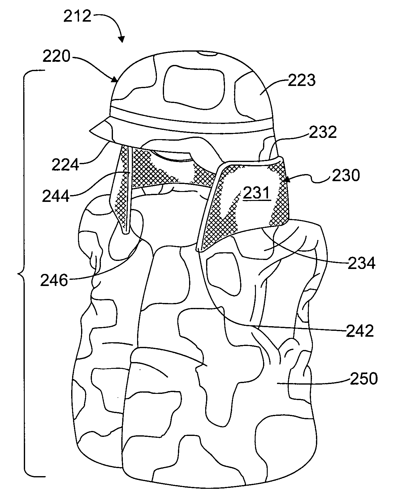
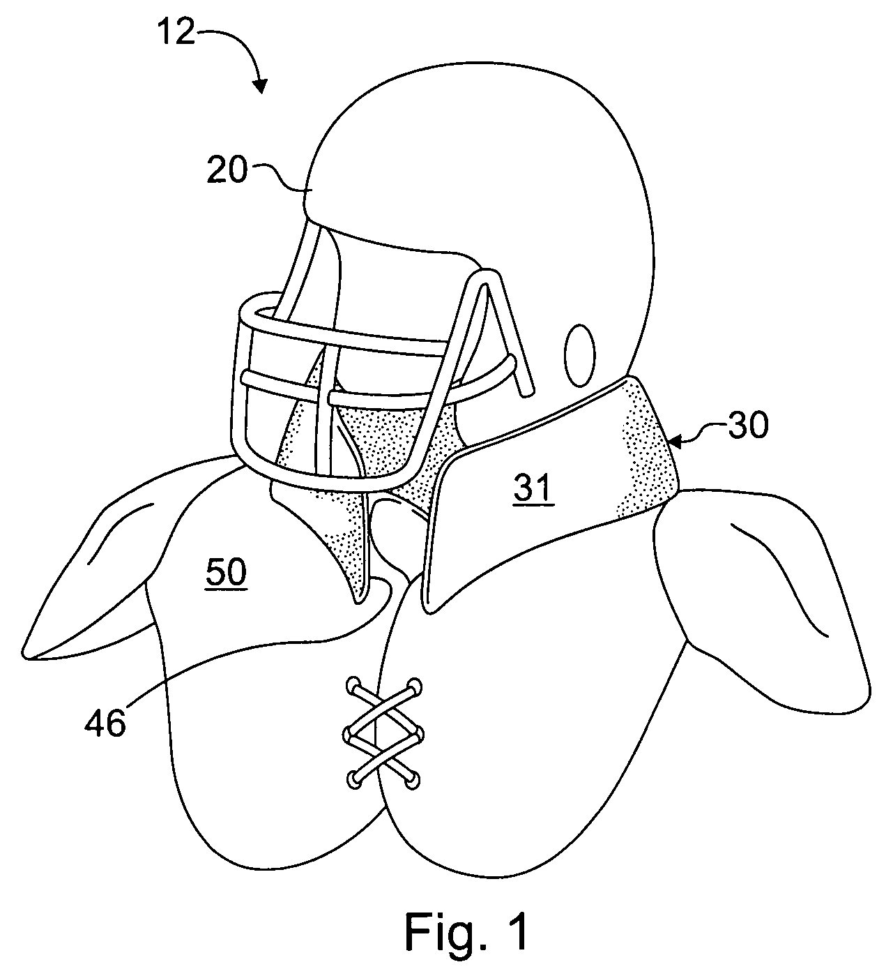
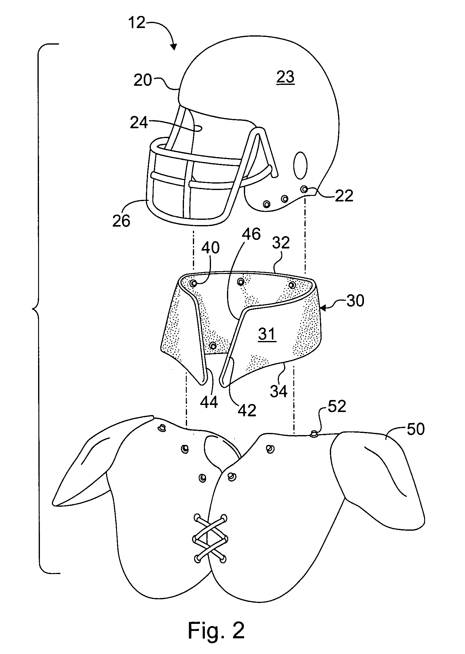
[0021] Referring to the drawing figures, and in particular to FIG. 1, a head and neck protection system 12 is shown. The protection system 12 includes a head protector 20, a neck guard 30, and shoulder gear 50. The neck guard 30 is connected between the head protector 20 and the shoulder gear 50 to form a shock-absorbing brace between the head protector and shoulder gear that substantially prevents hyperextension of the neck, hyperflexion of the neck, and other serious head and neck injury. The neck guard 30 is sufficiently flexible and light-weight to permit normal head rotation about the axis of the wearer's neck.

[0022] The protective system 12 is intended for use in a variety of activities that involve risk of injury to the head, neck and spine. For example, the protective system 12 may be used in a variety of sports and recreational activities, including but not limited to football, auto racing, motorcycling, lacrosse, and equestrian competition. Therefore, the protective syste...


PUM


Abstract

A head and neck protection system includes a head protector, a shoulder protector, and a neck guard for protecting a person from injury. The neck guard detachably connects between the head protector and the shoulder protector and includes a collar. The collar has a first edge and a second edge spaced apart from the first edge. The first and second edges include fastening means for detachably coupling the collar between the head protector and the shoulder protector. In one embodiment, the collar has a perimeter that flares outwardly as the collar extends from the head protector to the shoulder protector. The collar is formed of an anti-ballistic material to protect the person from injury from bullets, fragments and other projectiles. The collar interconnects the head protector with the shoulder protector to form a restraint that limits displacement of the head protector relative to the shoulder protector.

Description

RELATED APPLICATIONS [0001] This application is a continuation-in-part application of U.S. application Ser. No. 10 / 704,780 filed Nov. 10, 2003, the entirety of which is incorporated herein by reference.FIELD OF THE INVENTION [0002] The present invention relates generally to safety equipment, and particularly to protective gear for the head and neck that can be used in a variety of activities involving risk of injury. BACKGROUND [0003] Athletes use a variety of protective helmets and pads when participating in sports. For example, athletes who participate in football, lacrosse, hockey, auto racing and equestrian competition routinely use helmets for head protection. Safety standards for protective gear frequently conflict with other concerns, such as comfort. As a result, many head and neck guards sacrifice comfort for safety, or vice versa. A number of head and neck guards in the present state of the art have large bulky components that surround the head, neck and shoulders. Althoug...

Claims


Application Information

Patent Timeline
IPC IPC(8): A41D13/05A42B3/04A63B59/02A63B71/10A63B71/12
CPCA41D13/0512A42B3/0473A63B59/02A63B71/10A63B2243/007A63B2071/1208A63B2243/0045A63B2243/005A63B71/1291A42B3/105A63B2102/14A63B2102/24A63B59/20
Inventor AARON, TODD D.
Owner COOPER TECH CO
Learn More