
Torque direction detecting device for brushless motor

Inactive Publication Date: 2005-08-04
DENSO CORP
View PDF5 Cites 8 Cited by
  • Summary
  • Abstract
  • Description
  • Claims
  • Application Information

AI Technical Summary

Benefits of technology

[0010] It is an object of the invention to provide a simple, inexpensive and accurate torque direction detecting device for a brushless motor.

Problems solved by technology

However, these kinds of circuits makes the torque direction detecting device complicated and expensive.

Method used


Image

  • Torque direction detecting device for brushless motor
  • Torque direction detecting device for brushless motor
  • Torque direction detecting device for brushless motor

Examples


Embodiment Construction

[0025] A torque direction detecting device according to a preferred embodiment of the invention will be described with reference to appended drawings.

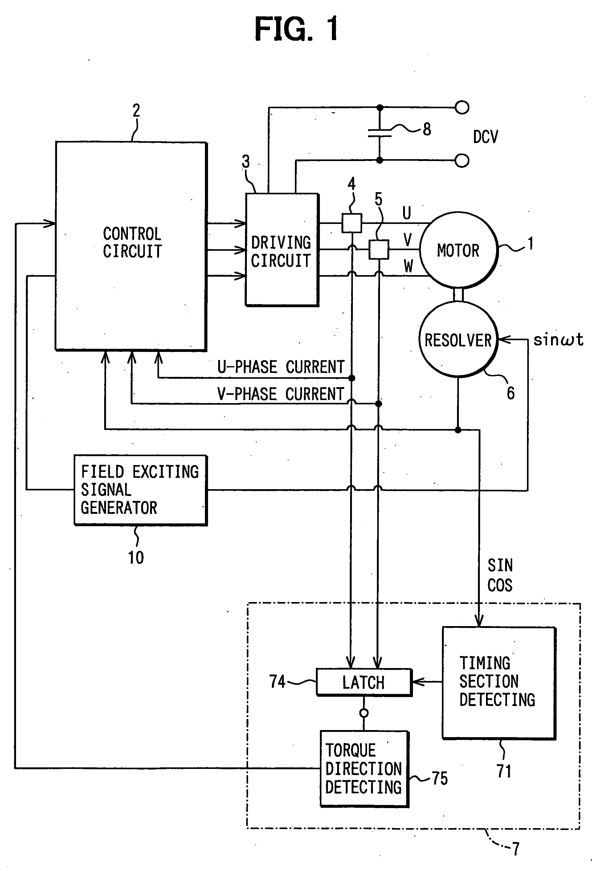
[0026] As shown in FIG. 1, a brushless motor control system includes a brushless motor1, a control circuit 2, a driving circuit 3 that includes a well-known three-phase inverter, current sensors 4, 5, a resolver 6, the torque direction detecting device 7 and a smoothing capacitor 8, a field exciting signal generator 10, etc.

[0027] The control circuit 2 provides three-phase gate control signals. The driving circuit 3 receives the gate control signals at the three-phase inverter and provides three-phase voltage signals, which are supplied to the brushless motor 1.

[0028] The resolver 6 includes a rotor fixed to the rotary shaft of the brushless motor l, a field coil mounted on the rotor, a stator core, a pair of stator windings mounted on the stator core at positions separated at 90 degrees in electric angle from each other. The field ...


PUM


Abstract

A torque direction detecting device for an electric motor includes a resolver which provides a pair of a sin θ signal and a cos θ signal with θ changing from 0 degree to 360 degrees in electric angle according to rotation of the brushless motor, a circuit which calculates an electric angle of the brushless motor from the sin θ signal and the cos θ signal, a current sensor for detecting phase current flowing through the phase windings, a circuit which provides a signal if the phase currents is in a prescribed magnitude relation, a circuit which divides a period of the 360 degree-electric angle into 8 timing sections according to magnitude relation between the sin θ signal and the cos θ signal and comparison of the sin θ signal and the cos θ signal with 0, and a circuit which determines a torque direction of the brushless motor if the comparison signal is provided in one of prescribed two timing sections each of which has a specific combination of the magnitude relation and the comparison of the sin θ signal and the cos θ signal.

Description

CROSS REFERENCE TO RELATED APPLICATION [0001] The present application is based on and claims priority from Japanese Patent Application 2004-025573, filed Feb. 2, 2004, the contents of which are incorporated herein by reference. BACKGROUND OF THE INVENTION [0002] 1. Field of the Invention [0003] The present invention relates to a torque direction detecting device for a brushless motor. [0004] 2. Description of the Related Art [0005] A brushless motors has been used in various control systems such as an electric power steering control system because of its simple mechanical structure and excellent controlling performance. In order to drive such a brushless motor, rotation position of the brushless motor's rotor is detected by a rotation position detector such as a resolver, which generates a rotating magnetic field. A control system and a three-phase bridge circuit are provided to drive the brushless motor according to the rotation position signal. The rotation position detector also ...

Claims


Application Information

Patent Timeline
IPC IPC(8): B62D5/00H02P6/06B62D5/04H02P1/18H02P6/08H02P6/16H02P6/17
CPCB62D5/008H02P21/04H02P21/0035B62D5/046H02P21/22
Inventor YAMAMOTO, TOSHIHISA
Owner DENSO CORP
Learn More