Leg type movable robot

a robot and leg technology, applied in the field of legged mobile robots, can solve problems such as adverse effects on the external appearance of legs

Active Publication Date: 2005-08-04
HONDA MOTOR CO LTD
View PDF8 Cites 26 Cited by
  • Summary
  • Abstract
  • Description
  • Claims
  • Application Information

AI Technical Summary

Benefits of technology

[0028] Thus, a stronger or larger drive force is required to rotate the ankle joint of the robot about the right-and-left axis (right-and-left direction perpendicular to the robot advancing direction) than to rotate the ankle joint about the back-and-forth axis (robot advancing direction). Therefore, generally a motor that is larger and heavier than the motor used to rotate the ankle joint about the back-and-forth axis is selected for the motor used to rotate the ankle joint about the right-and-left axis. Accordingly, as stated in claim 18 to be hereinafter described, a configuration is provided such that the second

Problems solved by technology

The reason the speed reducer is disposed at the shank link is because having too many components disposed at the thigh link may have an adverse effect o

Method used


Image

  • Leg type movable robot
  • Leg type movable robot
  • Leg type movable robot

Examples


second embodiment

[0073] Next, the legged mobile robot according to the present invention will be described.

[0074]FIG. 5 is a right-hand side view showing the distal end from the shank link of the leg in the legged mobile robot according to the second embodiment, and FIG. 6 is a right-hand side view similar to FIG. 4, showing the distal end from the shank link when the ankle Y-axis has been rotated −60 degrees.

first embodiment

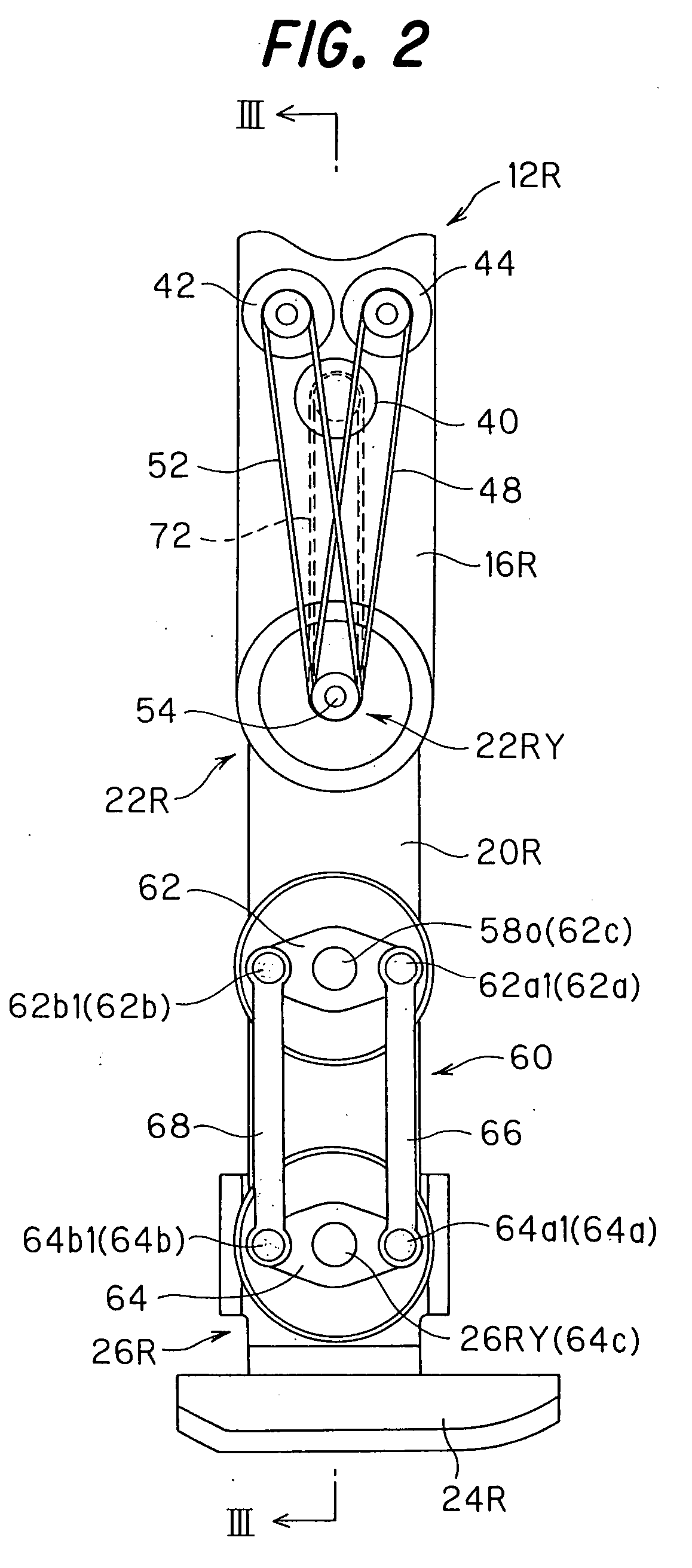
[0075] As described in the first embodiment, setting both the angle formed by the one end 62a, the midpoint 62c, and the other end 62b of the first crank, and the angle formed by the one end 64a, the midpoint 64c, and the other end 64b of the second crank to about 180 degrees has the advantage that no additional stress is applied to the bearing 84 for supporting the ankle Y-axis 26RY (26LY) because the transmissive force of the first crank and the transmissive force of the second crank balance each other out (constitute a couple of forces).

[0076] However, such a configuration has been inconvenient in that rotation becomes difficult (specifically, a dead point is present) when the one end 62a, the midpoint 62c, and the other end 62b of the first crank, and the one end 64a, the midpoint 64c, and the other end 64b of the second crank are all positioned along the same straight line.

[0077] In view of this, in the second embodiment, the angle formed by the one end 62a, the midpoint 62c, ...

third embodiment

[0081] Next, a legged mobile robot according to the present invention will be described.

[0082] In a legged mobile robot, the torque exerted on the ankle joint is generally determined by the gait pattern. In view of this, the third embodiment is configured such that the angle formed by the one end 62a, the midpoint 62c, and the other end 62b of the first crank, and the angle formed by the one end 64a, the midpoint 64c, and the other end 64b of the second crank vary in response to the gait pattern of the mobile robot 10, or, specifically, the angles are set based on the torque about the ankle Y-axes 26RY and 26LY determined from the gait pattern.

[0083]FIG. 7 is a right-hand side view similar to FIG. 5, showing the distal end from the shank link in the leg of a legged mobile robot according to the third embodiment. FIG. 8 is a right-hand side view showing the distal end from the shank link when the ankle Y-axis has been rotated a degrees.

[0084] Before the descriptions of FIGS. 7 and ...


PUM


Abstract

In a legged mobile robot (10) having a motor (42) that rotates the ankle joint (26R (26L)) about a right-and-left axis of the robot (26RY (26LY)) and a speed reducer (58) that reduces speed of an output of the motor, wherein the motor is disposed at a same position as the knee joint (22R (22L)) or at the thigh link (16R (16L)) such that the speed reducer is disposed at the shank link. With this, it becomes possible to reduce the weight of the distal end of the leg (12R (12L)) can be reduced, whereby enabling to reduce the inertial force generated in the leg during movement or locomotion of the robot.

Description

TECHNICAL FIELD TO WHICH THE INVENTION RELATES TO [0001] The present invention relates to a legged mobile robot, and more specifically relates to the leg of a legged mobile robot. BACKGROUND ART OF THE INVENTION [0002] The technique described in Japanese Patent 2592340 (page 5, left column, FIG. 2, FIG. 6, etc.) is a known example of the technique relating to a legged mobile robot, particularly to the leg of a legged mobile robot. In this prior art, the configuration is such that an electric motor (80) for driving a knee joint is disposed at a thigh link (70), an electric motor (88) for driving an ankle joint is disposed at a shank link (86), and speed reducers (84)(92) disposed coaxially with the joints are driven by belts (82)(90), whereby the drive force necessary for walking is obtained. [0003] When the legged mobile robot is moved, particularly when the robot is moved at a high speed, a strong inertial force is generated in the leg. Therefore, the weight of the leg, particularl...

Claims


Application Information

Patent Timeline
IPC IPC(8): B25J5/00B25J9/10B62D53/08B62D57/032
CPCB25J9/102Y10T74/20299B62D57/032B25J5/00
Inventor MIYAZAKI, SUSUMUOTANI, TOMOKO
Owner HONDA MOTOR CO LTD
Why Eureka
Try Eureka