Air hammer for a boring machine

a boring machine and air hammer technology, which is applied in the field of boring machines, can solve the problems of vibration occurring while moving up and down, shock increasing, and uneven striking force of the bit unit, so as to prevent the distribution of striking force and reduce the effect of inertial for

Active Publication Date: 2012-10-18
HANJIN D&B
View PDF6 Cites 1 Cited by
  • Summary
  • Abstract
  • Description
  • Claims
  • Application Information

AI Technical Summary

Benefits of technology

[0015]In the air hammer for a boring machine according to the present invention, when the piston hammer is moved up and down, the top and bottom ends of the piston are supported, thereby preventing a striking force from being distributed due to vibration of the piston hammer and reducing an inertial force when the piston hammer is moved upward.
[0016]In addition, when a pneumatic pressure is supplied to first and second chambers, the air is rapidly cooled at discharge outlets of first and second pneumatic pressure supply passages due to adiabatic expansion, thereby preventing the piston hammer from being damaged due to brittleness.

Problems solved by technology

However, for a hard-boring operation, it is necessary to demolish rocks under the ground by dropping a large-sized hammer, requiring additional equipment such as a pile driver.
Since the conventional air hammer is moved downward to performing a striking action in a state in which it is separated from a guide, a vibration may occur while moving up and down.
In particular, the air is rapidly cooled at a discharge outlet of the chamber due to adiabatic expansion, causing cracks.
In addition, since there is no change in the air for upward moving the piston at the top dead center when the air hammer is moved upward, the shock may become increased.
In addition, since a reaction force may become increased when the air hammer collides with the bit unit, the striking force of the bit unit may not be uniform.

Method used


Image

  • Air hammer for a boring machine
  • Air hammer for a boring machine
  • Air hammer for a boring machine

Examples


Embodiment Construction

[0024]Hereinafter, a bearing unit according to an embodiment of the present invention and a protection cover for a grass mower using the bearing unit will be described in detail with reference to the accompanying drawings.

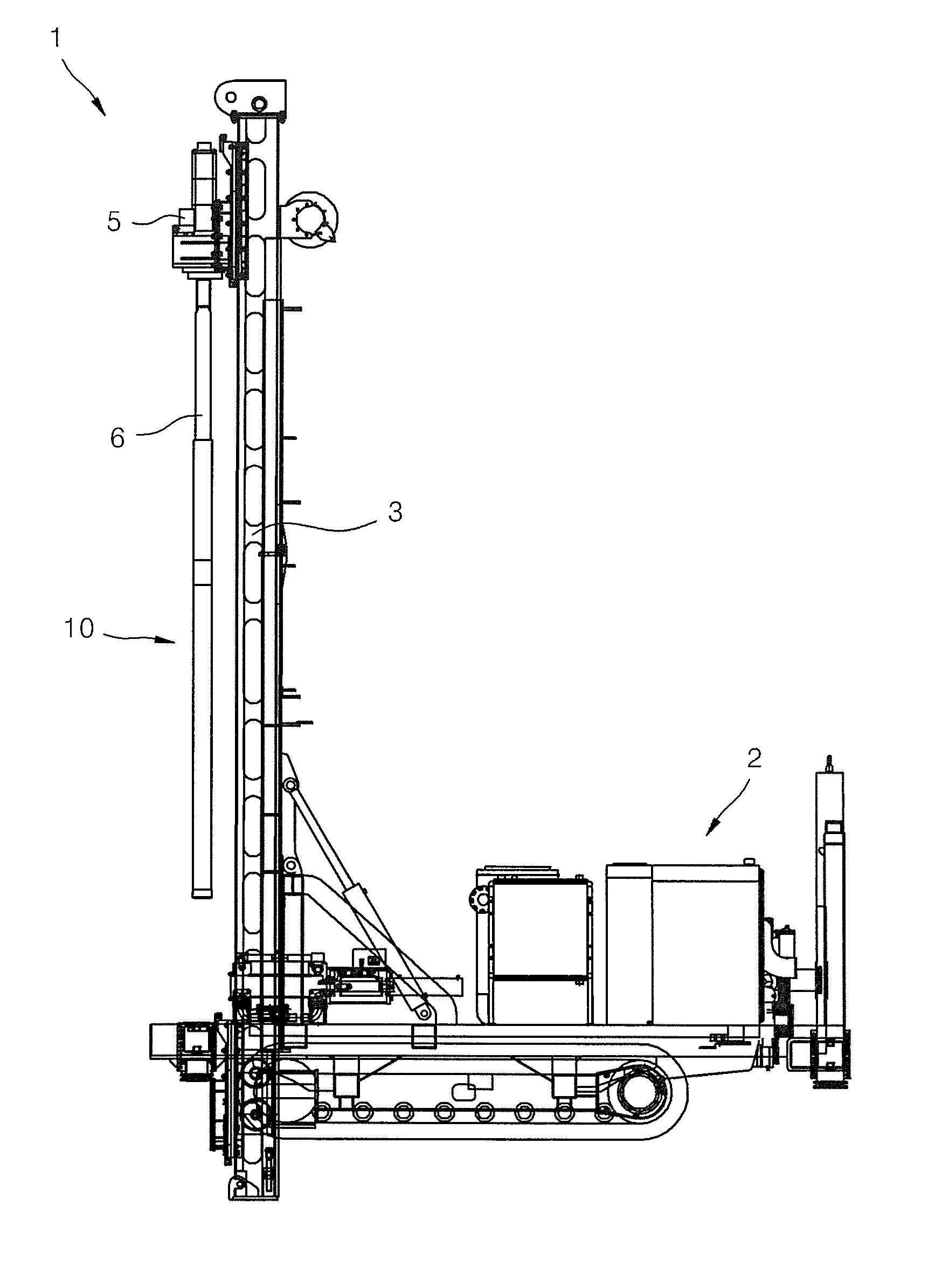
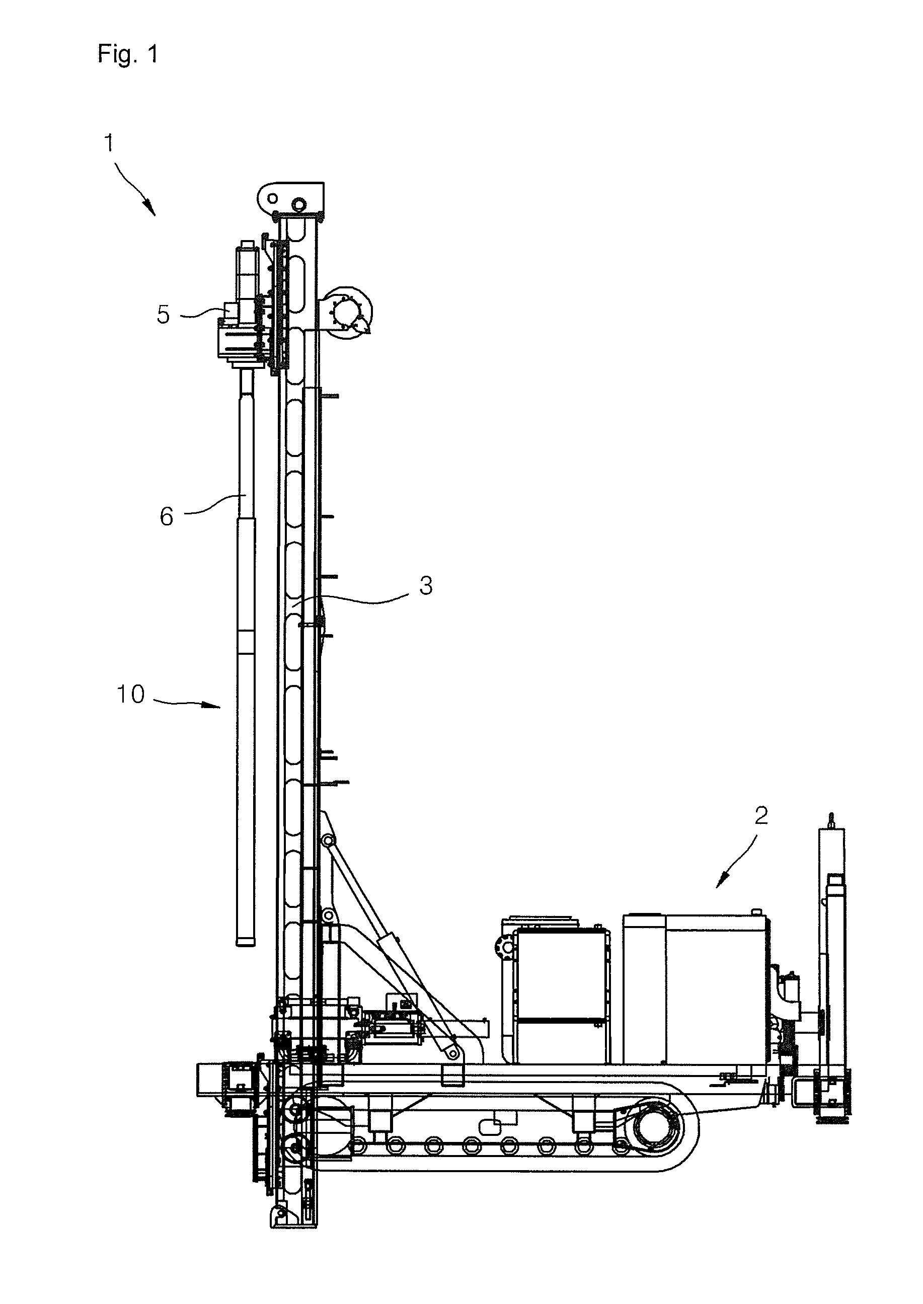
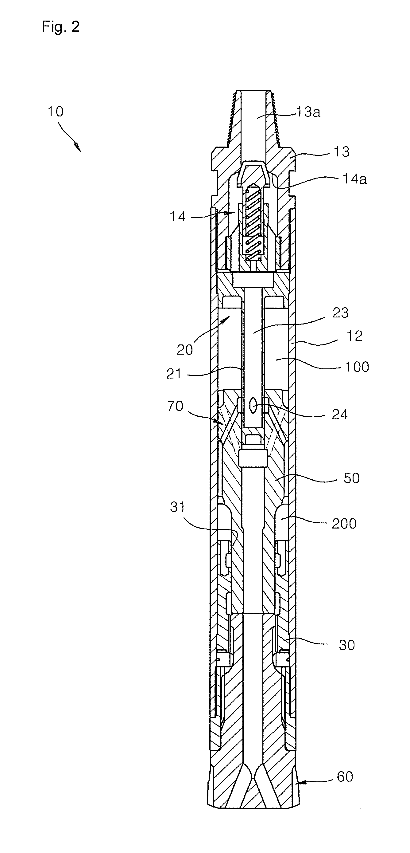
[0025]The air hammer according to the present invention is installed at a drive rod of a boring machine and supplies a bit with a striking force for performing excavation, and one example embodiment thereof is illustrated in FIGS. 1 and 2.

[0026]Referring to FIGS. 1 and 2, the boring machine 1 includes a lead 3 installed to be perpendicular to a machine body 2, a head part 5 guided by the lead 3 so as to be moved up and down, and an air hammer 10 coupled to a drive shaft of the head part 5 and installed at an end of a drive rod 6 so as to be moved up and down and to be rotated. Although not shown, a compressor for supplying the air hammer with a pneumatic pressure through the drive rod is installed in the machine body 2.

[0027]The air hammer 10 for the boring machine...


PUM

PropertyMeasurementUnit
diameteraaaaaaaaaa
pressureaaaaaaaaaa
areasaaaaaaaaaa

Abstract

An air hammer for a boring machine is provided, including: a main body including a hollow portion; a socket coupled to a side of the main body; a first bushing member including a sealing part coupled to the main body and a piston guide part extending from the sealing part in parallel with a lengthwise central axis of the main body and defining an air supply passage and discharge holes in an outer surface thereof to communicate with the air supply passage; a second bushing member installed at an end on the opposite side of the main body; a bit unit installed at an end of the second bushing member; a piston hammer, top and bottom ends of which are supported by the guide part and the second bushing member so as to be moved up and down, the piston hammer having a guide hole formed therethrough in the lengthwise direction and partitioning a main body compartment between the first and second bushing members into first and second chambers; a pneumatic discharge part formed at the top end of the second bushing member to discharge air in the second chamber when the piston hammer is moved upward; and a pneumatic pressure distribution part formed on the piston hammer to selectively supply to the first or second chamber, in conjunction with the socket, the pneumatic pressure supplied through a pneumatic pressure supply passage and the discharge holes of the piston guide part of the first bushing member.

Description

TECHNICAL FIELD[0001]The present invention relates to a boring machine, and more particularly, to an air hammer for a boring machine, which is installed at an end of a rod to perform excavation.BACKGROUND ART[0002]In general, a boring machine for perforating the ground is based on a technique of simply circulating a bit (Oscillating method), a technique of not only circulating a bit or a ball cutter but also pressurizing the same (Reverse Circulation Drilling method: ROC), and so on. According to the oscillating method, in a state in which a standard casing having a diameter of 800 to 3000 mm is clamped by a hydraulic chuck, boring is performed by oscillating a cylinder installed rotatably in a left-right direction. According to the ROC method, the ground is bored using a drive rod having a rotary bit or ball cutter installed at its end portion by rotating the bit or ball cutter. The oscillation method can cope with a soft ground condition, that is, excavation is properly carried ou...

Claims


Application Information

Patent Timeline
Patent Type & Authority Applications(United States)
IPC IPC(8): B25D9/00
CPCE21B4/14B25D9/00
Inventor IN, SUK SIN
Owner HANJIN D&B
Why Eureka
Try Eureka