
Method for making a disk drive head stack assembly having a tapered pivot bearing

a technology of disk drives and stack assemblies, applied in the field of disk drives, can solve the problems of affecting one or more aspects of the operation of the disk drive, requiring additional tooling, and requiring a large amount of labor, so as to reduce the inertial force, reduce the cost, and simplify the assembly procedure of the disk drive.

Inactive Publication Date: 2008-05-06
MAXTOR
View PDF14 Cites 16 Cited by
  • Summary
  • Abstract
  • Description
  • Claims
  • Application Information

AI Technical Summary

Benefits of technology

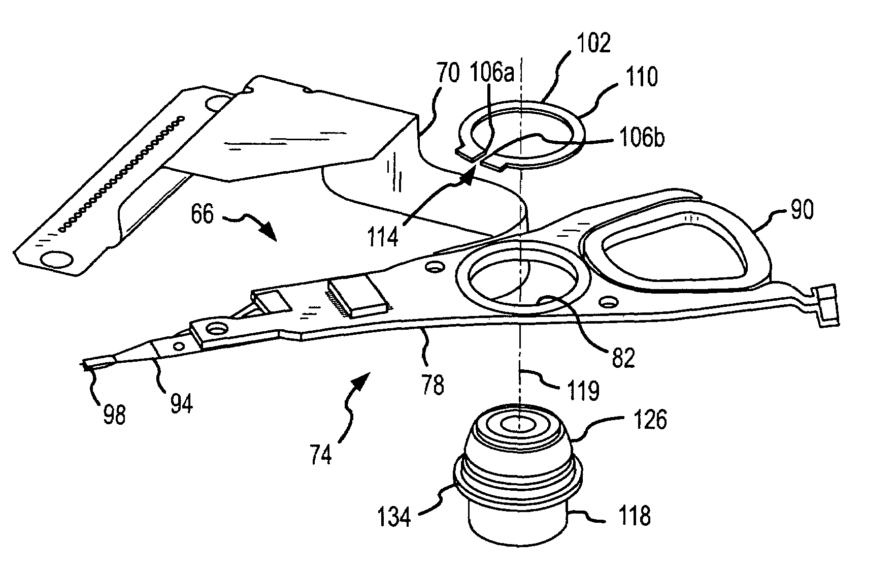
[0008]A first aspect of the present invention generally relates to a method for assembling a disk drive head stack assembly. A first actuator arm is mounted on an outer wall of the pivot bearing. A retainer ring, clip, or the like is used to mount the first actuator arm on the pivot bearing. In this regard, the retainer ring is disposed against a portion of the outer wall of the pivot bearing. The retainer ring is advanced relative to the pivot bearing in a direction of a retainer ring slot or groove formed on the outer wall of the pivot bearing. At least a portion of this advancement expands the retainer ring by its continued engagement with the pivot bearing to facilitate the disposition of the retainer ring within the retainer ring slot formed on the outer wall of the pivot bearing.
[0029]Various refinements exist of the features noted in relation to the sixth aspect of the present invention. Further features may also be incorporated in the sixth aspect of the present invention as well. These refinements and additional features may exist individually or in any combination. The noted pivot may be defined by a pivot bearing or cartridge bearing assembly which allows the actuator arm(s) to pivot / rotate relative to the encasement for the disk drive. One of the stops may be defined by the structure of this cartridge bearing assembly (e.g., a flange formed on an end portion thereof), while another of the stops may be defined by a retaining ring or the like which is detachably connected to the cartridge bearing assembly. In this case an annular groove, slot or the like may be formed about the pivot shaft for receipt of this retaining ring and against which the noted spring(s) may act to compress the actuator arm assembly stack. This simplifies the assembly procedure of the disk drive, and thereby reduces costs. Particulate amounts within the disk drive should also be reduced in relation to disk drives which use threaded connections to clamp the actuator arm assembly stack together.
[0030]Each actuator arm utilized by the sixth aspect may include an aperture through which the noted pivot shaft extends such that each actuator arm encircles the pivot shaft. Each actuator arm preferably includes a substantially planar surface in at least proximity to the pivot shaft to provide a suitable surface with radius of contact over which a frictional interface may be established with adjacent components in the stack through the axially-directed load provided by the noted spring(s). Preferably each actuator arm is of at least substantially uniform thickness. Minimizing the thickness of each actuator arm will also reduce inertial forces, which will in turn further reduces the potential for relative radial movement between components of the actuator arm assembly stack which is being maintained by the compressive forces of the spring(s).

Problems solved by technology

Both of the above-noted designs suffer from a number of disadvantages in at least some respect.
Solid actuator bodies with load beams separately attached thereto can be relatively costly to fabricate, assemble, test, and rework.
Threaded interconnections increase the potential for the generation of particulates within the disk drive encasement which can adversely affect one or more aspects of its operation.
However, it still requires additional tooling.

Method used


Image

  • Method for making a disk drive head stack assembly having a tapered pivot bearing
  • Method for making a disk drive head stack assembly having a tapered pivot bearing
  • Method for making a disk drive head stack assembly having a tapered pivot bearing

Examples


Embodiment Construction

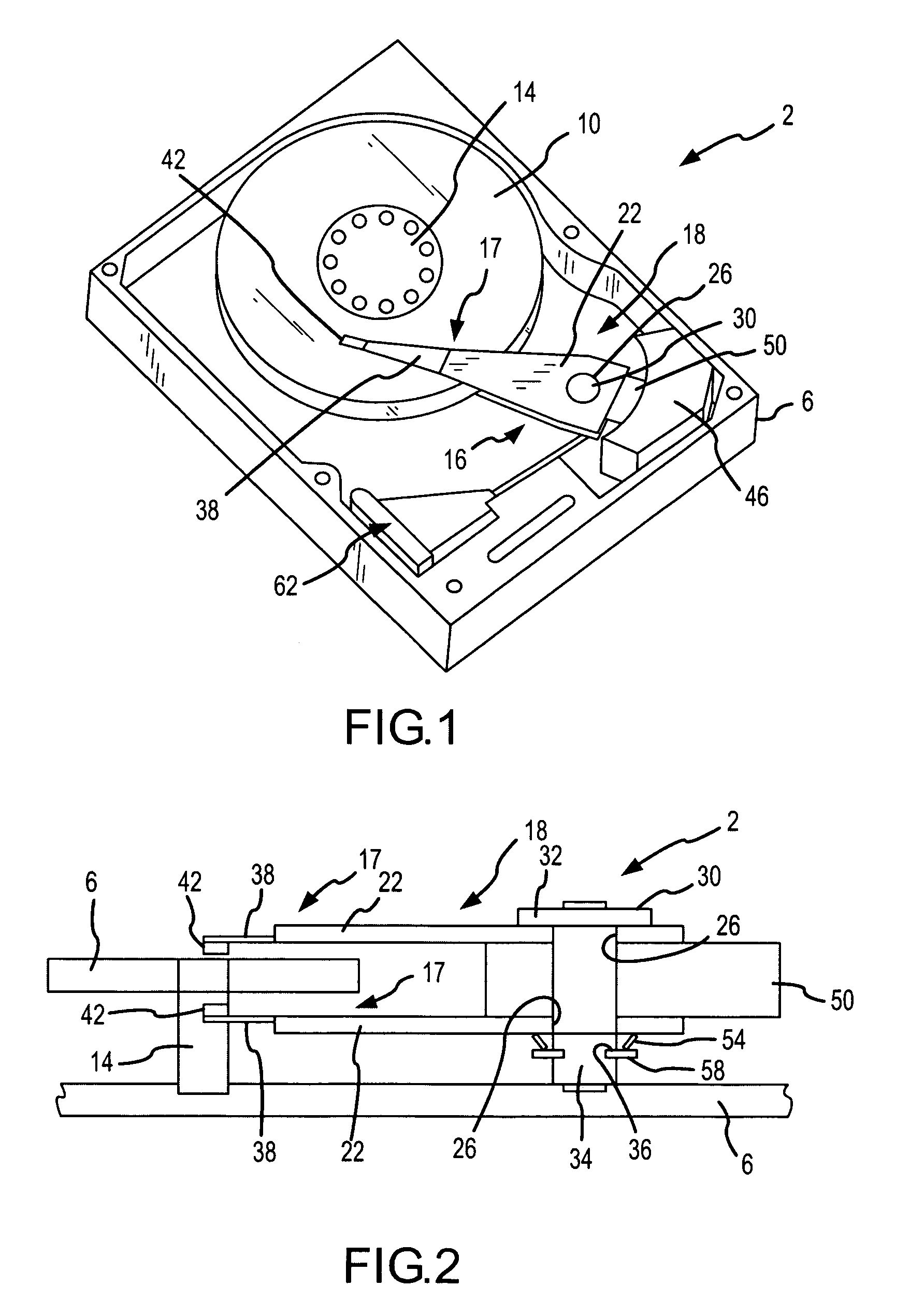
[0044]The present invention will now be described in relation to the accompanying drawings which at least assist in illustrating its various pertinent features. FIG. 1 presents a disk drive 2 having a disk drive housing defined by a base plate 6 and a cover that is appropriately attached thereto (not shown). The disk drive 2 generally includes a disk 10 of an appropriate computer-readable storage medium and a head stack assembly 16 for reading information from and writing information to the disk 10. The disk 10 is mounted on a rotatable spindle 14 for rotation by an appropriate motor (not shown) within an at least substantially horizontal reference plane. Typically the disk 10 will include a plurality of tracks which are concentrically disposed about the spindle 14 and which may be used to store information in discrete regions of the disk 10.

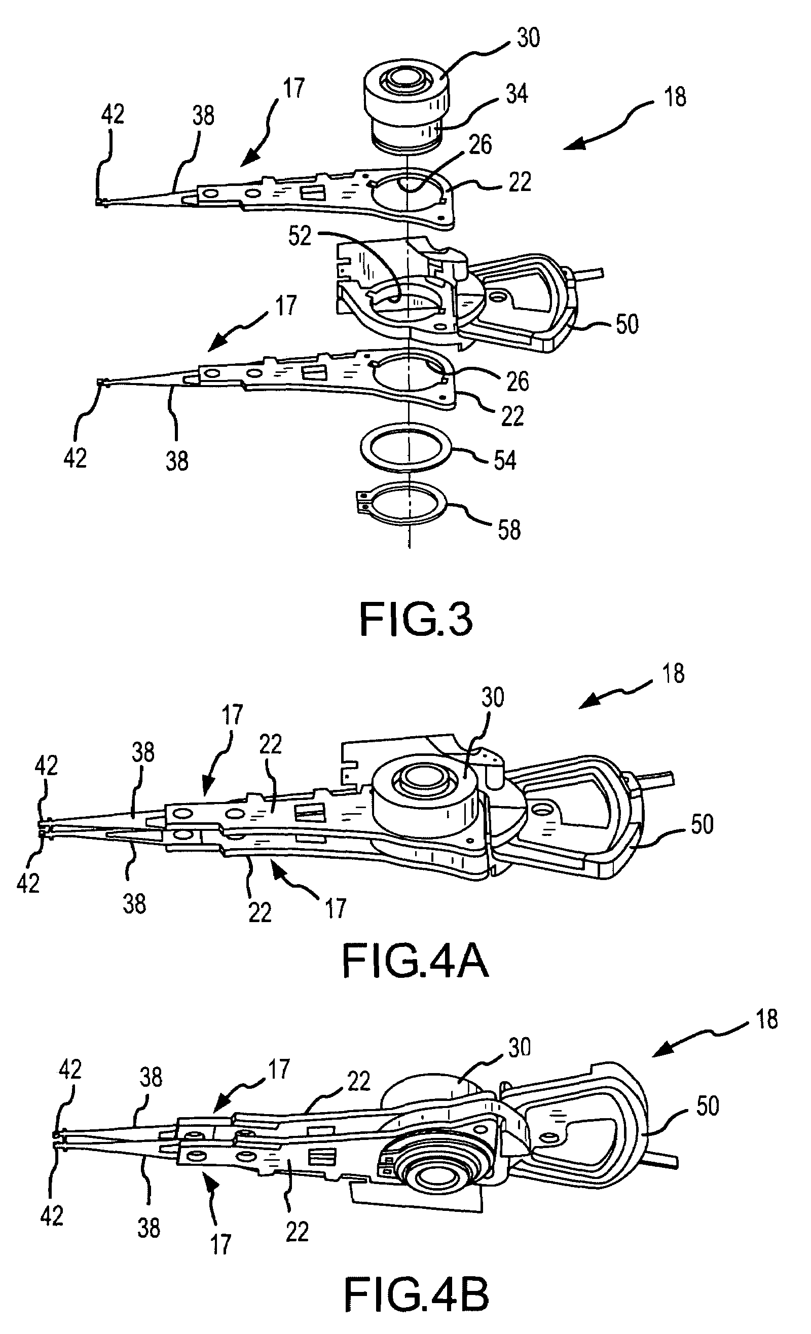
[0045]The head stack assembly 16 includes a head / arm assembly stack 18. Referring now to FIGS. 2-4B as well, the stack 18 includes two individu...


PUM

PropertyMeasurementUnit
distanceaaaaaaaaaa
diameteraaaaaaaaaa
timeaaaaaaaaaa

Abstract

A disk drive head stack assembly (66) of a configuration that facilitates the assembly thereof is disclosed. One or more head / arm assemblies (74) are mounted on a pivot bearing (118). This pivot bearing (118) includes a tapered section (126). Each head / arm assembly (74) may be mounted on the pivot bearing (118). Thereafter, a retainer ring (102) may be advanced relative to the pivot bearing (118). Advancement of the retainer ring (102) along the tapered section (126) expands the retainer ring (102) so that the same may be disposed within a retainer ring slot (130) of the pivot bearing (118). Each head / arm assembly (74) is maintained between this retainer ring (102) and a flange (134) of the pivot bearing (118).

Description

CROSS REFERENCE TO RELATED APPLICATIONS[0001]This patent application is a divisional of, and claims priority under 35 U.S.C. §120 to, U.S. patent application Ser. No. 10 / 412,884, that is entitled “DISK DRIVE HEAD STACK ASSEMBLY HAVING A TAPERED PIVOT BEARING”, and that was filed on Apr. 14, 2003, now U.S. Pat. No. 6,903,903, which is a continuation-in-part of, and claims priority under 35 U.S.C. §120 to, U.S. patent application Ser. No. 09 / 354,400, that is entitled “ACTUATOR ARM ASSEMBLY STACK COMPRESSED WITH SPRING WASHER,” and that was filed on Jul. 15, 1999, now abandoned. The entire disclosure of each of these applications is incorporated by reference in their entirety herein.FIELD OF THE INVENTION[0002]The present invention generally relates to disk drives and, more particularly, to using at least one retainer ring to at least generally assist in maintaining an association of at least one head / arm assembly and a pivot bearing during disk drive operations (e.g., read and / or writ...

Claims


Application Information

Patent Timeline
Patent Type & Authority Patents(United States)
IPC IPC(8): G11B5/127H04R31/00
CPCG11B5/4826Y10T29/49027Y10T29/4903Y10T29/49025
Inventor FRUGE, TAVE J.DUNCKLEY, JAMES A.
Owner MAXTOR
Learn More