
Collapsible structure

a technology of collapsible structures and cylinders, which is applied in the direction of rigid containers, sacks, transportation and packaging, etc., can solve the problems of large devices in their expanded state, relatively large devices in their collapsed state, and difficult manipulation, so as to achieve more space, consume more materials, and facilitate manipulation

Inactive Publication Date: 2005-08-04
SPORTPET DESIGNS
View PDF99 Cites 19 Cited by
  • Summary
  • Abstract
  • Description
  • Claims
  • Application Information

AI Technical Summary

Benefits of technology

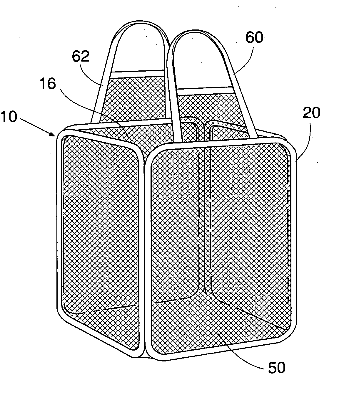
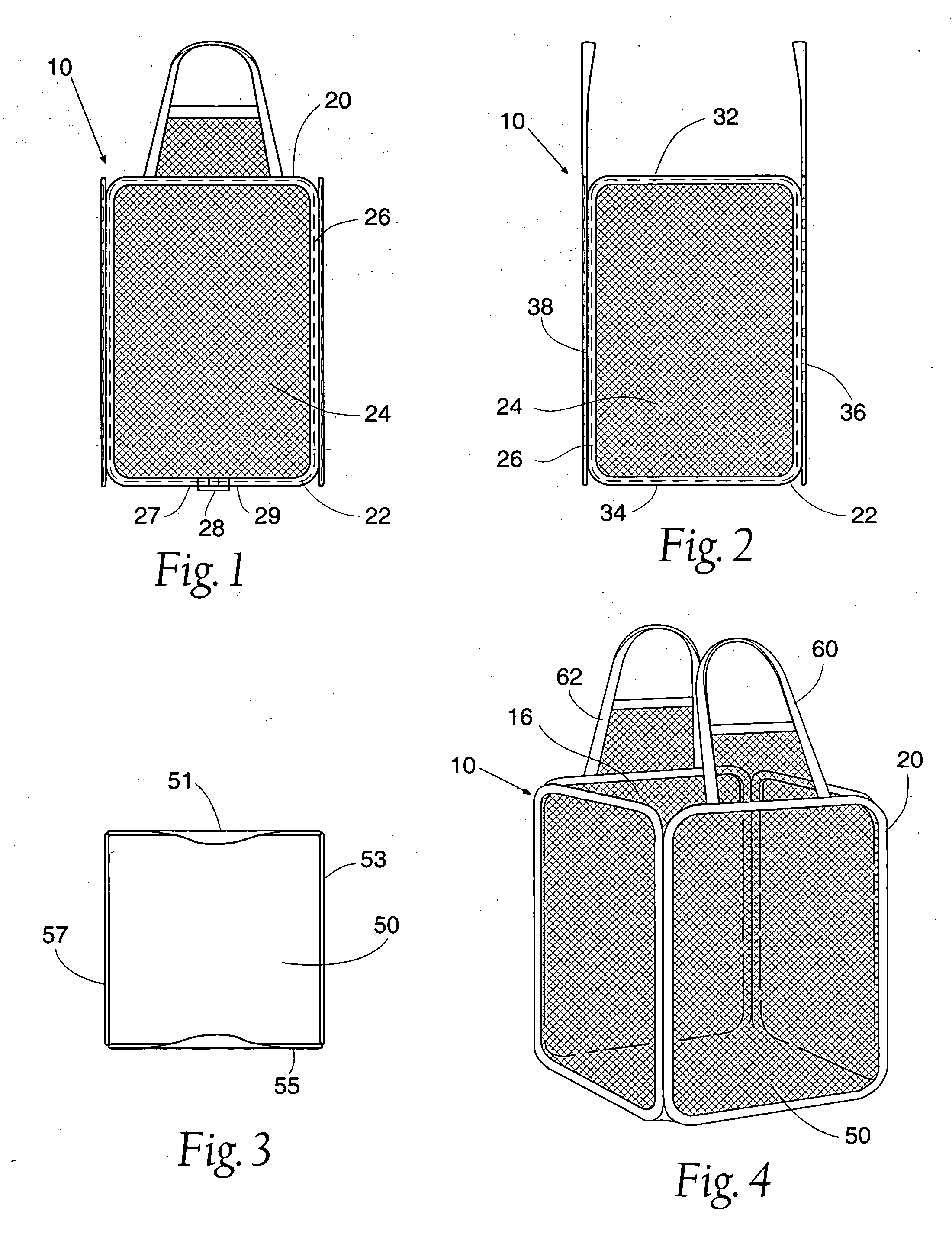
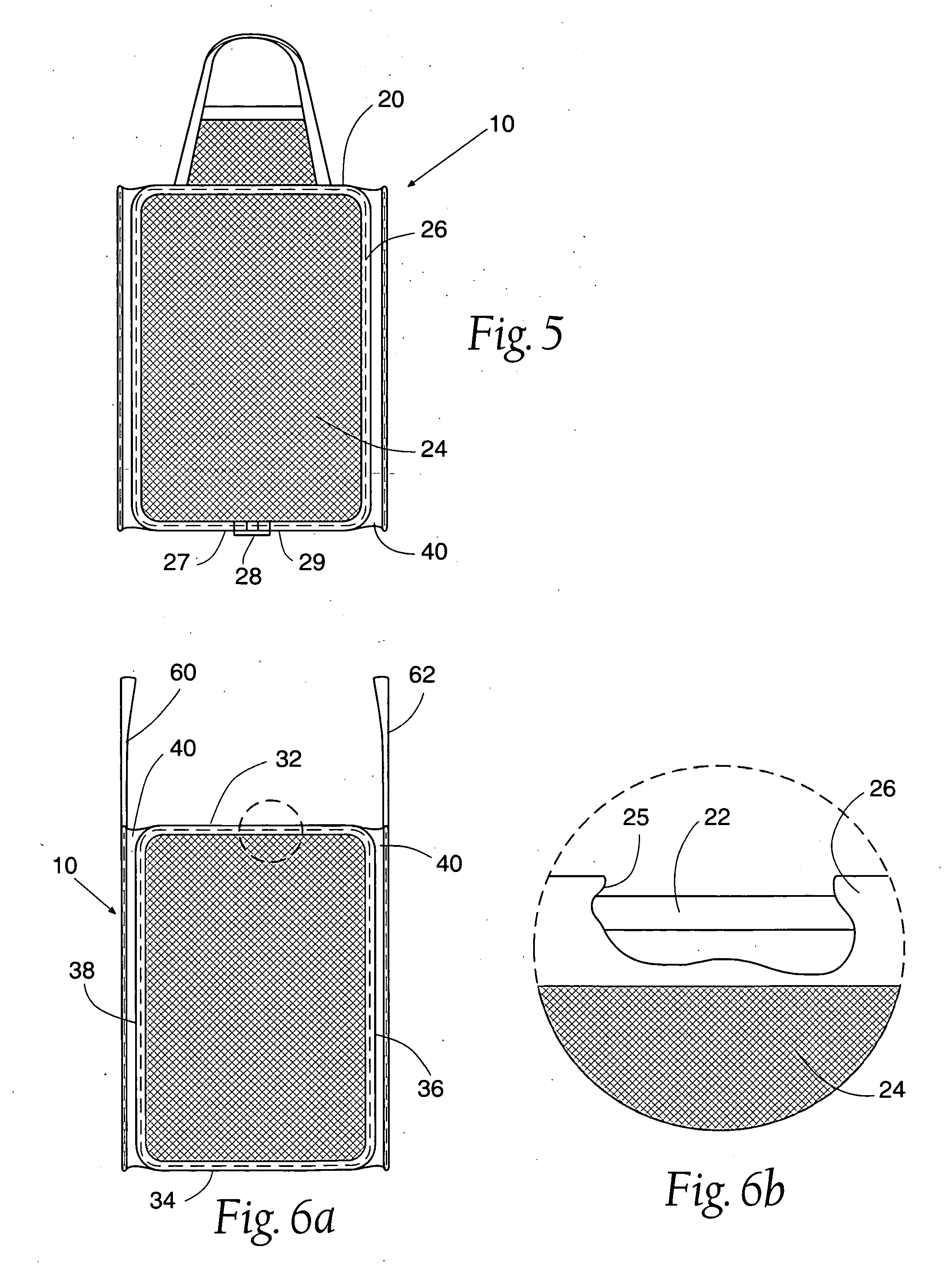
[0011] In an alternative embodiment, each side panel is attached to a side panel separator, which in turn is connected to the next adjacent side panel. The floor panel is attached to both the bottom side of each side panel and to the side panel separators, thus providing means for holding articles within the structure and for supporting the structure in its expanded state.
[0014] In accordance with another aspect of the invention, an optional storage pouch may be coupled to one of the side panels at the open top of the structure. The present invention is easily collapsed into a compact state and the pouch allows storage of the structure in its collapsed, compact state.
[0024] In an alternative embodiment, each of the top panel, bottom panel, and two side panels are attached to a side panel separator, which in turn is connected to the next adjacent panel. The front panel is attached to both the front side of the top panel, bottom panel, and two side panels, and to the side panel separators. The rear panel is attached to both the rear side of the top panel, bottom panel, and two side panels, and to the side panel separators, thus providing means for holding pets or other objects within the enclosure and for supporting the enclosure in its expanded state.
[0035] From the expanded state, the enclosure can be folded and collapsed for storage or transportation. The preferred steps of collapsing the enclosure include grasping opposite corners of the rear panel or front panel and biasing one corner toward the other until the top panel, bottom panel, and two side panels are adjacent and overlay each other. The enclosure is now partially collapsed but the top panel, bottom panel, and two side panels each are still in an expanded state. Next, the optional handle members and the rear panel and front panel are inserted in between any two of the adjacent overlaying expanded panels. By rotating two opposite corners of the flattened, overlaying panels in opposite directions while biasing the two corners toward each other, the enclosure will form three overlaying circular loops folded adjacently. Finally, the three overlaying loops may be placed into an optional storage pouch. The pouch prevents the enclosure from springing back into its fully expanded condition. Alternatively, the three overlaying loops may be maintained in the collapsed state by way of an elastic band or other retaining device.

Problems solved by technology

However, all these prior art devices are voluminous in their expanded state, are uneasy to fold or collapse, are still relatively voluminous in their collapsed state, and are difficult to manipulate.
These devices commonly have a square footprint and a domed configuration, which creates a pet enclosure that is larger than necessary because of unutilized space.
As the size of the enclosure increases, its cost increases and its integrity decreases.
All these prior art pet enclosures are voluminous in their expanded state, are either non-collapsible or are uneasy to fold or collapse, are still relatively voluminous in their collapsed state, and are difficult to manipulate.
These configurations require more space, consume more materials, and require stronger collapsible framing than are necessary to efficiently contain or transport a pet or other objects.

Method used


Image

  • Collapsible structure
  • Collapsible structure
  • Collapsible structure

Examples


fifth embodiment

[0047]FIG. 14 is a front plan view of the collapsible structure, namely a two-compartment structure.

[0048]FIG. 15 is a side plan view of a fifth embodiment of the collapsible structure.

[0049]FIG. 16 is a top plan view of a fifth embodiment of the collapsible structure.

[0050]FIG. 17 is a perspective view of a fifth embodiment of the collapsible structure.

sixth embodiment

[0051]FIG. 18 is a front plan view of the collapsible structure, namely a three-compartment structure.

[0052]FIG. 19 is a side plan view of a sixth embodiment of a fifth embodiment of the collapsible structure.

[0053]FIG. 20 is a top plan view of a sixth embodiment of the collapsible structure.

[0054]FIG. 21 is a perspective view of a sixth embodiment of the collapsible structure.

[0055]FIGS. 22A through 30 depict the preferred method of manufacturing the collapsible structure.

[0056]FIGS. 31 through 36 depict the method of collapsing the collapsible structure.

seventh embodiment

[0057]FIG. 37 is a front plan view of the collapsible structure, namely a structure having two frame members.

[0058]FIG. 38 is a side plan view of the collapsible structure seen in FIG. 37.

[0059]FIG. 39 is a top plan view of the collapsible structure shown in FIG. 37.

[0060]FIG. 40 is a perspective view of the collapsible structure shown in FIG. 37.

[0061]FIG. 41 is a front plan view of another alternative embodiment of the collapsible, two-frame structure showing seam covers over the frame insertion points.

[0062]FIG. 42 is a side plan view of the collapsible structure shown in FIG. 41.

[0063]FIG. 43 is a perspective view of the collapsible structure shown in FIG. 41.

[0064]FIG. 44 is a side plan view of a pair of side panels.

[0065]FIG. 45 is a side plan view of the side panels with the edging partially attached.

[0066]FIG. 46 is a side plan view of the side panels with the edging attached.

[0067]FIG. 47 is a side plan view of the side panels and edging with the frame member being...


PUM


Abstract

A collapsible structure having a top panel, bottom panel, side panels, a front panel, and a rear panel releasibly attached and forming an enclosure having a door. Each top, bottom, and side panel comprises a two-ply web of material and a removably seated continuous loop frame. One or more handles may be attached to the structure or formed within one or more of the panels. A method of making and collapsing the structure is also disclosed.

Description

RELATED APPLICATIONS [0001] This is a continuation-in-part patent application of U.S. patent application Ser. No. 10 / 413,925 filed 15 Apr. 2003 now pending and not abandoned, which is a continuation-in-part of U.S. patent application Ser. No. 09 / 834,437 filed 13 Apr. 2001 now abandoned, which is a continuation-in-part of U.S. patent application Ser. No. 09 / 698,674 filed on 27 Oct. 2000 that has since issued to U.S. Pat. No. 6,494,335, which is a continuation-in-part of U.S. patent application Ser. No. 09 / 393,956 filed on 10 Sep. 1999 now abandoned, which is a continuation-in-part of U.S. patent Parent application Ser. No. 09 / 108,521 filed on 1 Jul. 1998 that has since issued to U.S. Pat. No. 5,971,188, now RE37,924 issued 10 Dec. 2002; the pending application and the issued patents are commonly owned by the assignee hereof.BACKGROUND OF THE INVENTION [0002] The present invention relates generally to collapsible structures and specifically to a collapsible container for convenient st...

Claims


Application Information

Patent Timeline
Patent Type & Authority Applications(United States)
IPC IPC(8): B65D6/18B65D6/20D06F95/00
CPCD06F95/004
Inventor KELLOGG, MICHAEL S.KROTTS, DEAN B.
Owner SPORTPET DESIGNS
Learn More