Supercharge Your Innovation With Domain-Expert AI Agents!

Apparatus for adjusting inclination of chair backs

a technology for adjusting the inclination and the chair back, which is applied in the direction of the mechanical control device, the instrument, the chair, etc., can solve the problems of unsmooth and uneasy operation of the control rod, and achieve the effects of convenient and simple operation, enhanced positioning plate movement force, and convenient operation for users

Active Publication Date: 2005-08-04
TUNG YU OA
View PDF8 Cites 3 Cited by
  • Summary
  • Abstract
  • Description
  • Claims
  • Application Information

AI Technical Summary

Benefits of technology

[0006] Making the movements of the positioning plate smoother and the operation easier and simpler for users is exactly the objective of this invention. Therefore, the present invention adopts a power-saving lever structure to control the control rod and achieve the purpose of an easy operation and greatly enhance the force to move the positioning plate.
[0007] The present invention also designs the direction for applying a force by the spring to push the positioning plate in the same direction as the moving direction of the positioning plate, such that the pushing force applied to the positioning plate by the spring can be acted completely onto the positioning plate without any loss, and thus making the movement of the positioning plate smoother.

Problems solved by technology

Since the direction of applying force to operate the control rod and the direction of the reaction of the spring have the same axial direction, which will make the operation of the control rod unsmooth and uneasy, particularly when a larger force is needed to operate the control rod.

Method used


Image

  • Apparatus for adjusting inclination of chair backs
  • Apparatus for adjusting inclination of chair backs
  • Apparatus for adjusting inclination of chair backs

Examples


Embodiment Construction

[0015] The detailed description and technical characteristics of the present invention are described together with the drawings as follows.

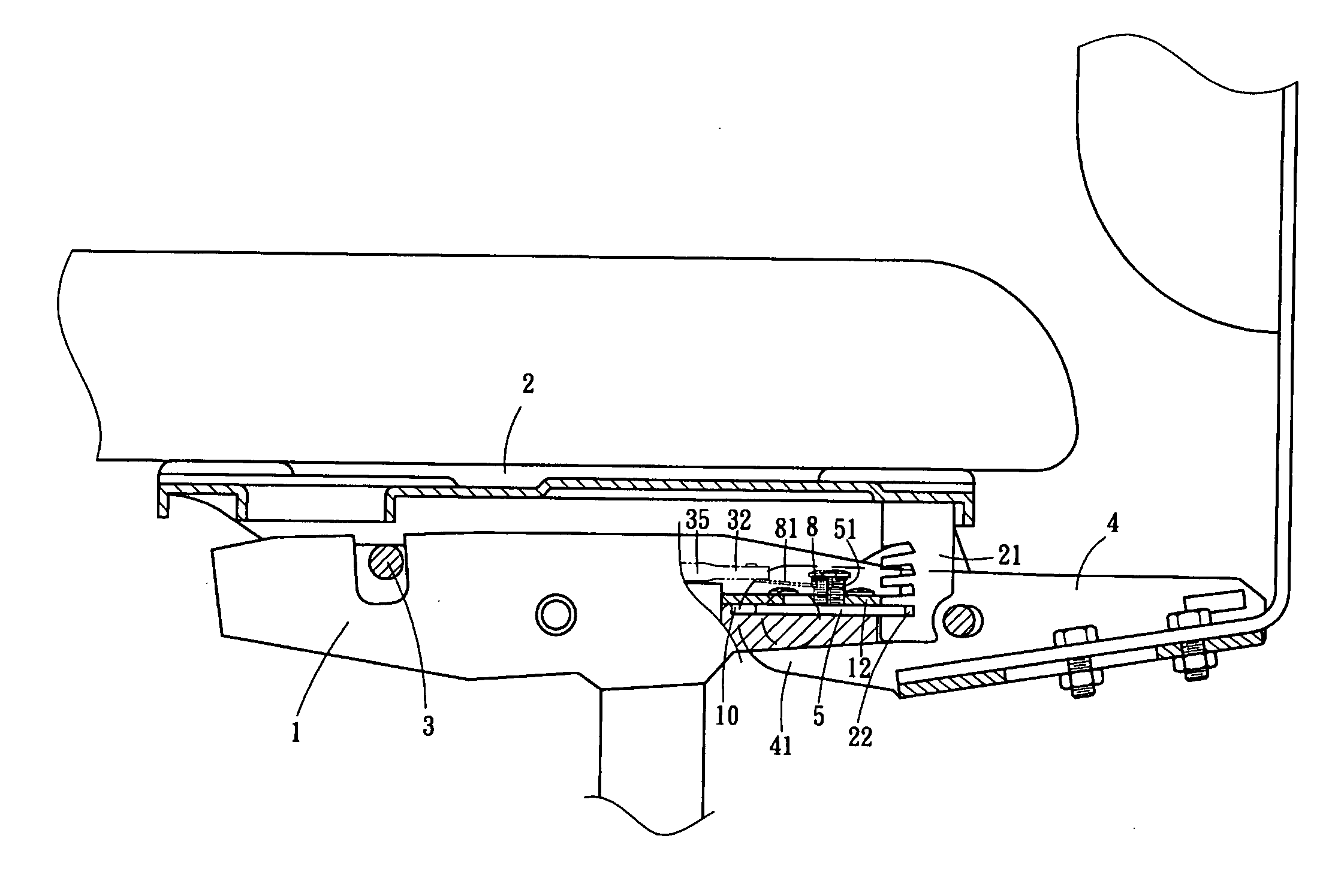
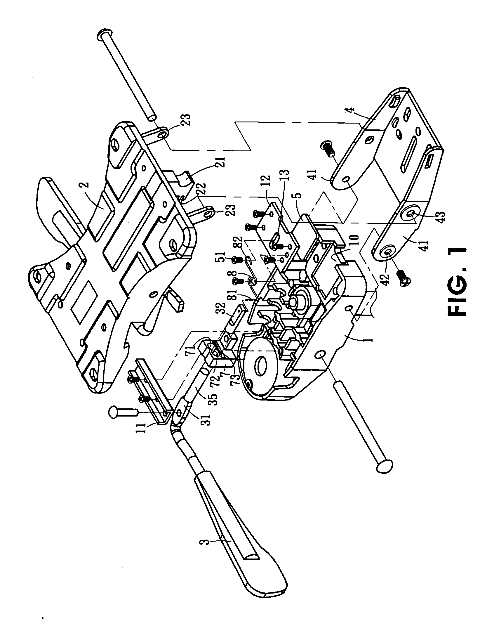
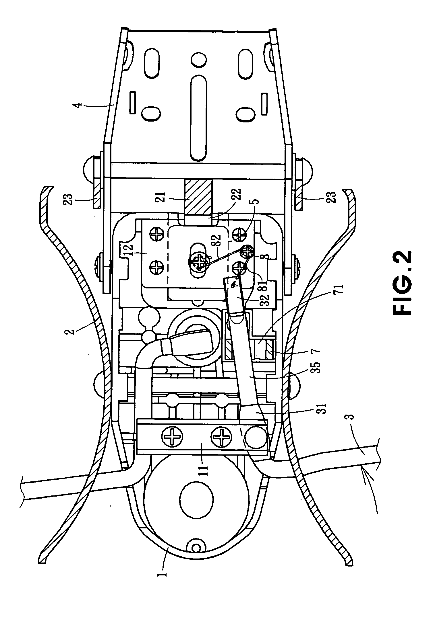
[0016] Please refer to FIGS. 1, 2, and 3 for the present invention. The apparatus for adjusting the inclination of a chair back comprises a base 1 disposed at the upper end of a chair leg, a chassis 2 disposed at the bottom of a cushion of a chair, such that the base 1 and the chassis 2 are pivotally coupled together in the middle, and the rear end of the base 1 is pivotally coupled to a through hole 42 at the front end 41 of a swing frame 4. A through hole 43 disposed on both sidewalls of the swing frame 4 is pivotally coupled to a link arm 23 extended from both sides at the rear side of the chassis 2, and a positioning member 21 is fixed to the middle section of the bottom at the rear side of the chassis 2, and a plurality of latch grooves 22 is disposed on the positioning member 21.

[0017] Further, an end of a control rod 3 is extended out fr...


PUM


Abstract

An apparatus for adjusting the inclination of a chair back, is disposed on the chassis at the bottom of a cushion and pivotally coupled to the middle of a base at the upper end of chair legs. A control rod has its middle predetermined position pivotally coupled to the base. A positioning plate has a bolt at its top surface and is disposed at the rear end of the base. A resilient component is pivotally coupled such that one end of the resilient component is hooked into an end of the control rod, and the other end of the resilient component being hooked into the bolt at the top surface of the positioning plate. When the control rod is turned to swing its end, the resilient component rotates, so that one of the resilient legs of the resilient component produces an elastic push onto the positioning plate. Thus the positioning plate contracts and moves to embed into or withdrawal from a latch groove disposed at the bottom rear side of the chassis. Therefore, the pushing force of a spring can be acted completely on the positioning plate and the positioning plate can move smoother, making operation easier and simpler.

Description

FIELD OF THE INVENTION [0001] The present invention relates to an apparatus for adjusting an inclination of chair backs, more particularly to an apparatus comprising a control rod disposed on the base of a chair with a rotary end, a contractible fixing plate being slidably embedded into or withdrawn from a latch opening disposed at any position on the rear side of the chassis fixed on the bottom of a seat cushion for adjusting the inclination of a chair back. BACKGROUND OF THE INVENTION [0002] The R.O.C. Patent No. 496133 disclosed an apparatus for controlling the inclination of a chair back, comprising: an air pressure rod disposed at the upper end of a chair leg and having an end passing through a base; a chassis with a cushion disposed on the base; the fixed base and chassis being pivotally coupled together; a plurality of latch grooves extended downward from the rear side of the chassis; a guide base disposed on the base and having a groove for accommodating a positioning plate;...

Claims


Application Information

Patent Timeline
Patent Type & Authority Applications(United States)
IPC IPC(8): A47C1/024A47C1/026A47C1/032A47C7/00A47C7/40G05G5/06
CPCA47C1/03255A47C1/03238
Inventor HONG, LIN YU
Owner TUNG YU OA
Features
  • R&D
  • Intellectual Property
  • Life Sciences
  • Materials
  • Tech Scout
  • Unparalleled Data Quality
  • Higher Quality Content
  • 60% Fewer Hallucinations
Learn More