Fault tolerant linear actuator

a linear actuator and fault-tolerant technology, applied in the field of linear actuators, can solve the problems loss of life or high cost, and achieve the effect of reducing the number of possible single-point failures, and reducing the number of possible failures

Inactive Publication Date: 2005-08-04
BOARD OF RGT THE UNIV OF TEXAS SYST
View PDF0 Cites 25 Cited by
  • Summary
  • Abstract
  • Description
  • Claims
  • Application Information

AI Technical Summary

Benefits of technology

[0011] In accordance with one aspect of the present invention, a fault tolerant linear actuator is provided that incorporate velocity summing, force summing, or a combination of the two. In one embodiment, the invention offers a velocity summing arrangement with a differential gear between two prime movers driving a cage, which then drives a linear spindle screw transmission. This embodiment is reconfigurable, but since it has only one transmission, it does not eliminate all possible single point failures. A second embodiment features two prime movers driving separate linear spindle screw transmissions (one internal and one external) in a totally concentric and compact integrated module. This system has no single point failures, which is desirable where failure would result in loss of life or high cost. A third embodiment uses two rotary actuators driving acme screws in place of the linear spindle screw transmission to make a very rugged high force system. A fourth embodiment is a force summing linear actuator based on a dual set of linear spindle screw drives summing forces through two clutches at the output attachment plate. A fifth embodiment uses an intermediate gear train between the input prime movers and the output spindle screws in order to better balance the torque / speed ratios and to enable a significantly higher motor speed than in the second embodiment. This two-stage reduction also allows for a significant reduction in the weight of the actuator.
[0012] The development of certain technologies makes it possible for the electromechanical actuators of the present invention to surpass the performance of prior known designs in essentially every aspect of performance. As an example, the commercial availability of the roller spindle screw transmission is a significant step forward in performance. As another example, the development of modern highly-integrated circuits allows for increases in performance and reductions in cost at the same time. Using these and other technologies, the present invention not only offers high load capacity, it also offers very long life, high precision, and high velocity in a compact configuration and the potential for a high level of actuator intelligence.
[0013] Intelligence within the actuator itself makes it possible to balance operational priorities (speed, load, precision, smoothness, etc.) in real time. Intelligence within the actuator permits the system of the present invention to be highly fault tolerant. This fault tolerance depends on a full awareness of all the performance capabilities of the actuator in real time. This awareness requires access to a wide spectrum of sensors, each generating data quantifying performance criteria used to judge the actuator's operation. Depending on the application, these performance criteria may be prioritized to meet in-situ operational goals. Here, the principal goal is to maintain operation under a fault. Depending on the operational requirements, the output of a faulty prime mover in an actuator may be quantified and used as a basis to temporarily raise the performance of the one or more fully-operational prime movers in order to make up for the loss of performance from the faulty prime mover. Alternately, the faulty prime mover may be taken completely out of service by braking it and “limping home” using the remaining prime movers.
[0014] The teachings of the present invention may be employed in any application in which there is the potential for loss of life, a need to preserve a long mission in harsh environments without possibility of repair, or a potential for high cost resulting from sudden failure. This layered control should combine to give more precise operation under significant load disturbances.

Problems solved by technology

This embodiment is reconfigurable, but since it has only one transmission, it does not eliminate all possible single point failures.
This system has no single point failures, which is desirable where failure would result in loss of life or high cost.

Method used


Image

  • Fault tolerant linear actuator
  • Fault tolerant linear actuator
  • Fault tolerant linear actuator

Examples


Embodiment Construction

[0022] Although making and using various embodiments of the present invention are discussed in detail below, it should be appreciated that the present invention provides many inventive concepts that may be embodied in a wide variety of contexts. The specific aspects and embodiments discussed herein are merely illustrative of ways to make and use the invention, and do not limit the scope of the invention.

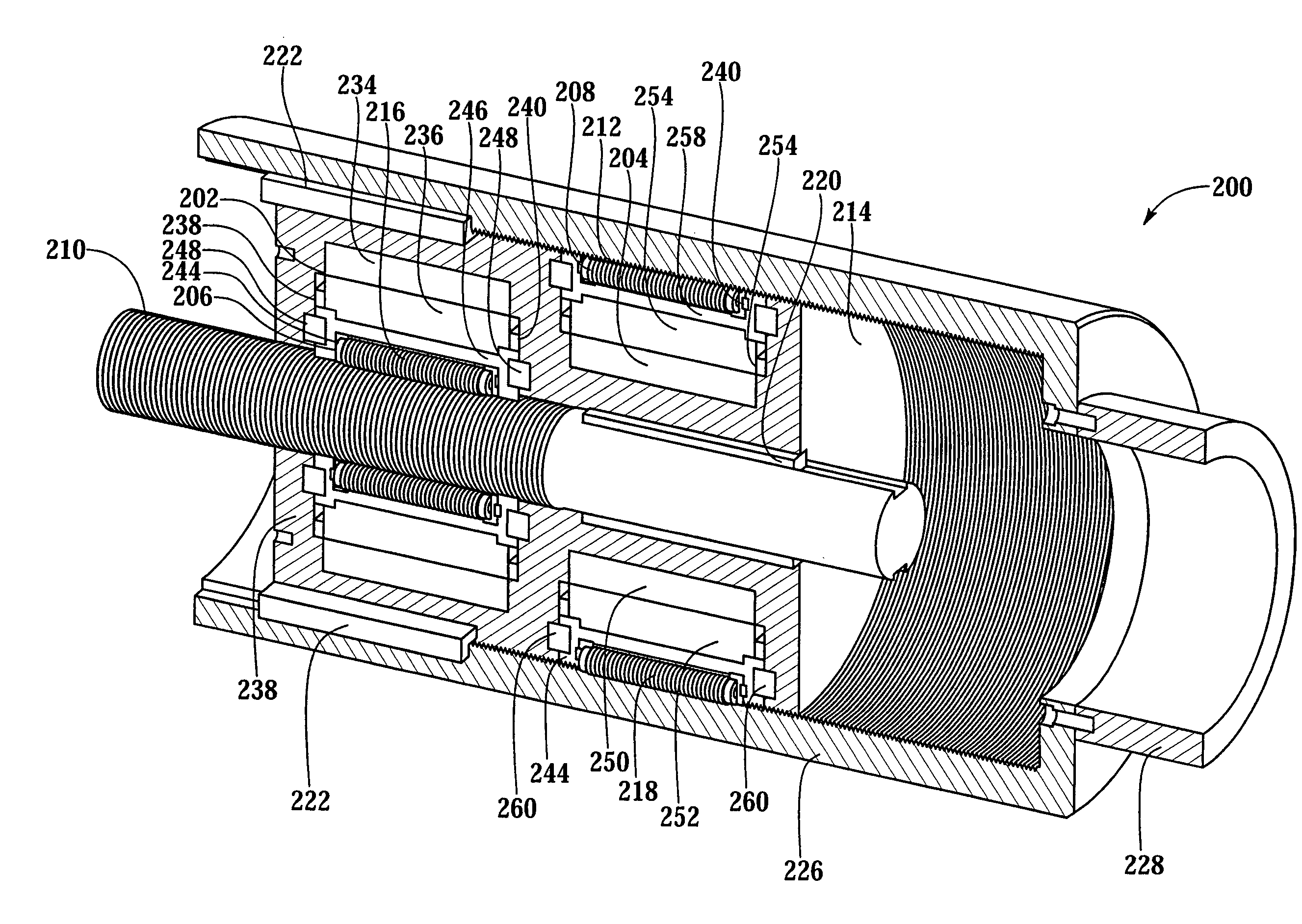
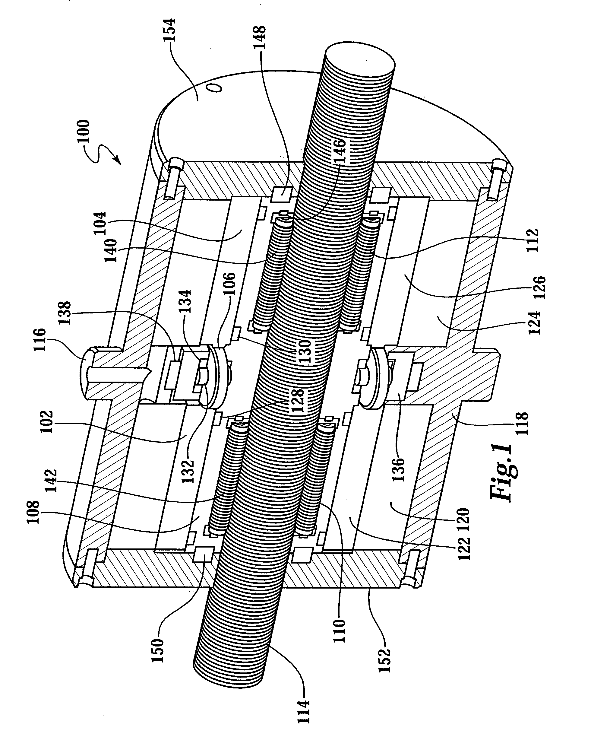
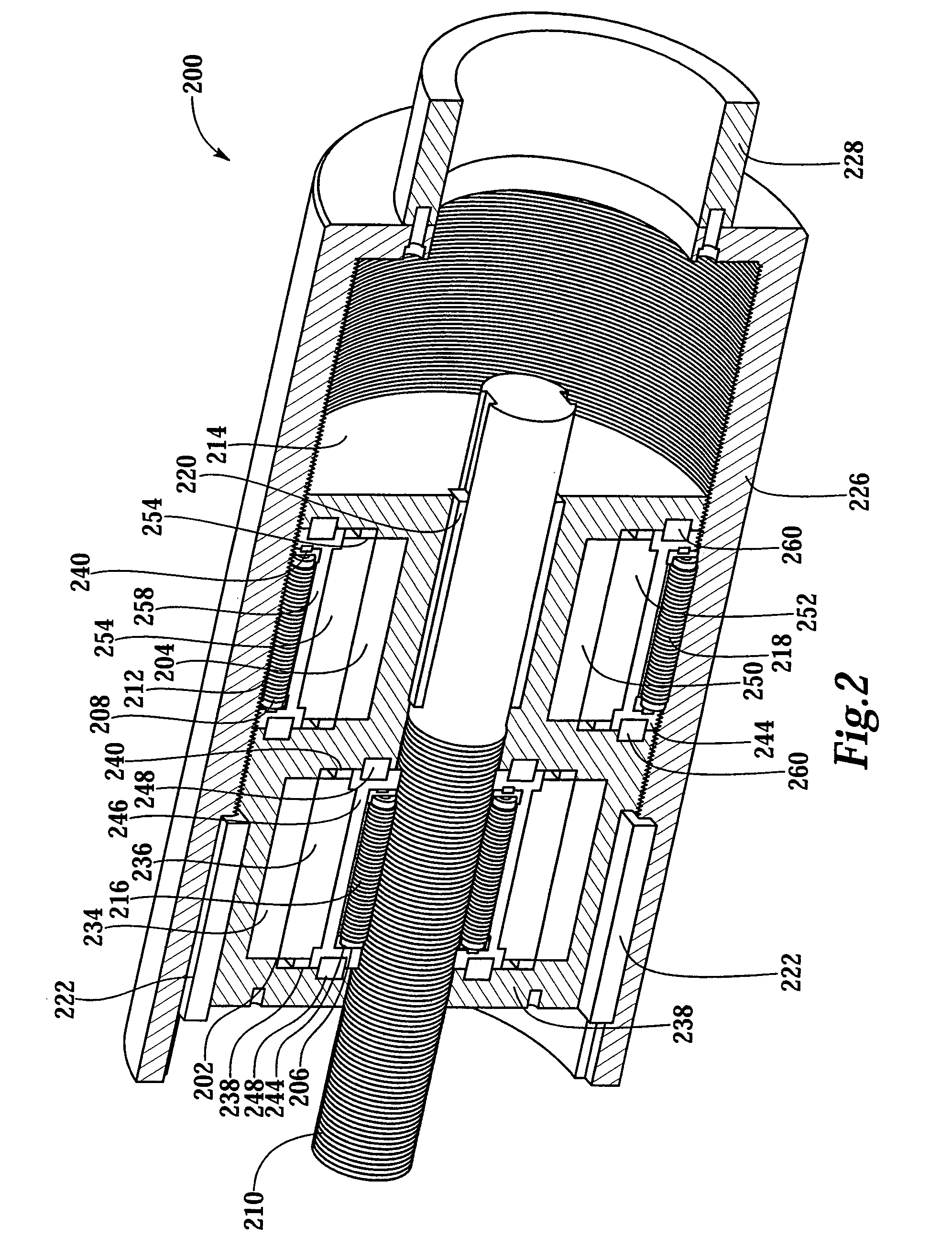
[0023]FIG. 1 depicts an isometric cutaway view of a velocity summing fault tolerant linear actuator 100 according to one embodiment of the present invention. Actuator 100 provides a dual set of prime movers 102 and 104 operating through a differential gearset 106, which then drives a cage 108 containing two sets of spindle screw drives 110 and 112 operating on a single linear output screw 114. Fault tolerant linear actuator 100 is fault tolerant up to the differential gearset 106, e.g., either prime mover 102 or 104 may be disabled (e.g., braked) and the remaining prime mover 102 or...


PUM


Abstract

In varying embodiments, the fault tolerant linear actuator of the present invention is a new and improved linear actuator with fault tolerance and positional control that may incorporate velocity summing, force summing, or a combination of the two. In one embodiment, the invention offers a velocity summing arrangement with a differential gear between two prime movers driving a cage, which then drives a linear spindle screw transmission. Other embodiments feature two prime movers driving separate linear spindle screw transmissions, one internal and one external, in a totally concentric and compact integrated module.

Description

[0001] The U.S. Government may own certain rights in this invention pursuant to the terms of the U.S. Department of Energy grant number DE-FG04-94EW37966. This application claims priority to U.S. Provisional Patent Application Ser. No. 60 / 386,661, filed Jun. 5, 2002.BACKGROUND OF THE INVENTION [0002] The present invention relates generally to electro-mechanical actuators, and specifically to a linear actuator having improved fault tolerance and positional control. [0003] A number of approaches have been developed to manipulate the linear position of an object or device through the use of an actuator. Linear actuators are pervasive where the movement of very large loads is required. Linear actuation has traditionally been met by the use of hydraulic and pneumatic cylinders. Electromagnetic actuators are known, however, to provide increased performance in many aspects as compared to either hydraulic or pneumatic cylinders. [0004] One drawback to the use of electromagnetic actuators is...

Claims


Application Information

Patent Timeline
Patent Type & Authority Applications(United States)
IPC IPC(8): F16H25/22H02K7/06H02K7/116
CPCF16H25/205F16H25/2252F16H2025/2078H02K7/06H02K2213/06Y10T74/186
Inventor TESAR, DELBERT
Owner BOARD OF RGT THE UNIV OF TEXAS SYST
Why Eureka
Try Eureka