
Lighting device and lighting system

Inactive Publication Date: 2005-08-04
PIONEER CORP
View PDF14 Cites 23 Cited by
  • Summary
  • Abstract
  • Description
  • Claims
  • Application Information

AI Technical Summary

Benefits of technology

[0010] An object of the present invention is to provide a lighting device and a lighting system capable of easily setting lighting condition with a simple configuration.

Problems solved by technology

As a result, when the lighting device is used as light sources of the button switches disposed along the curved surface, distances from each of the button switches to the light sources become different from each other, with the result that illuminance levels of the button switches differ form each other.
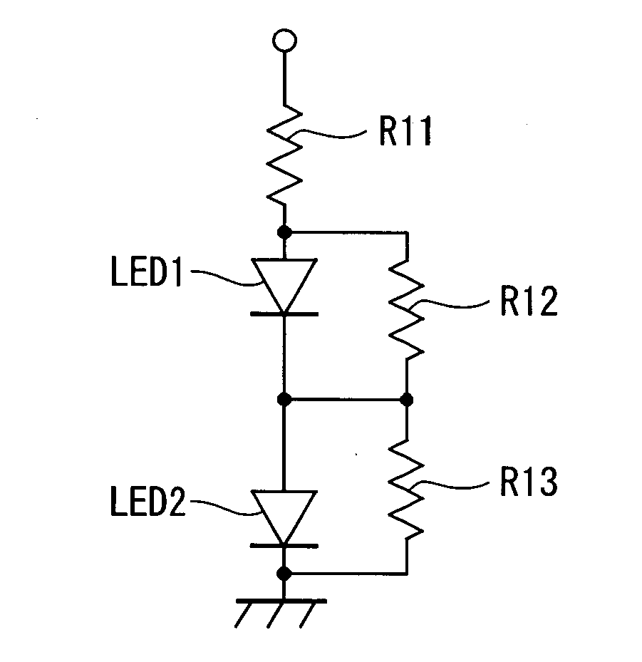
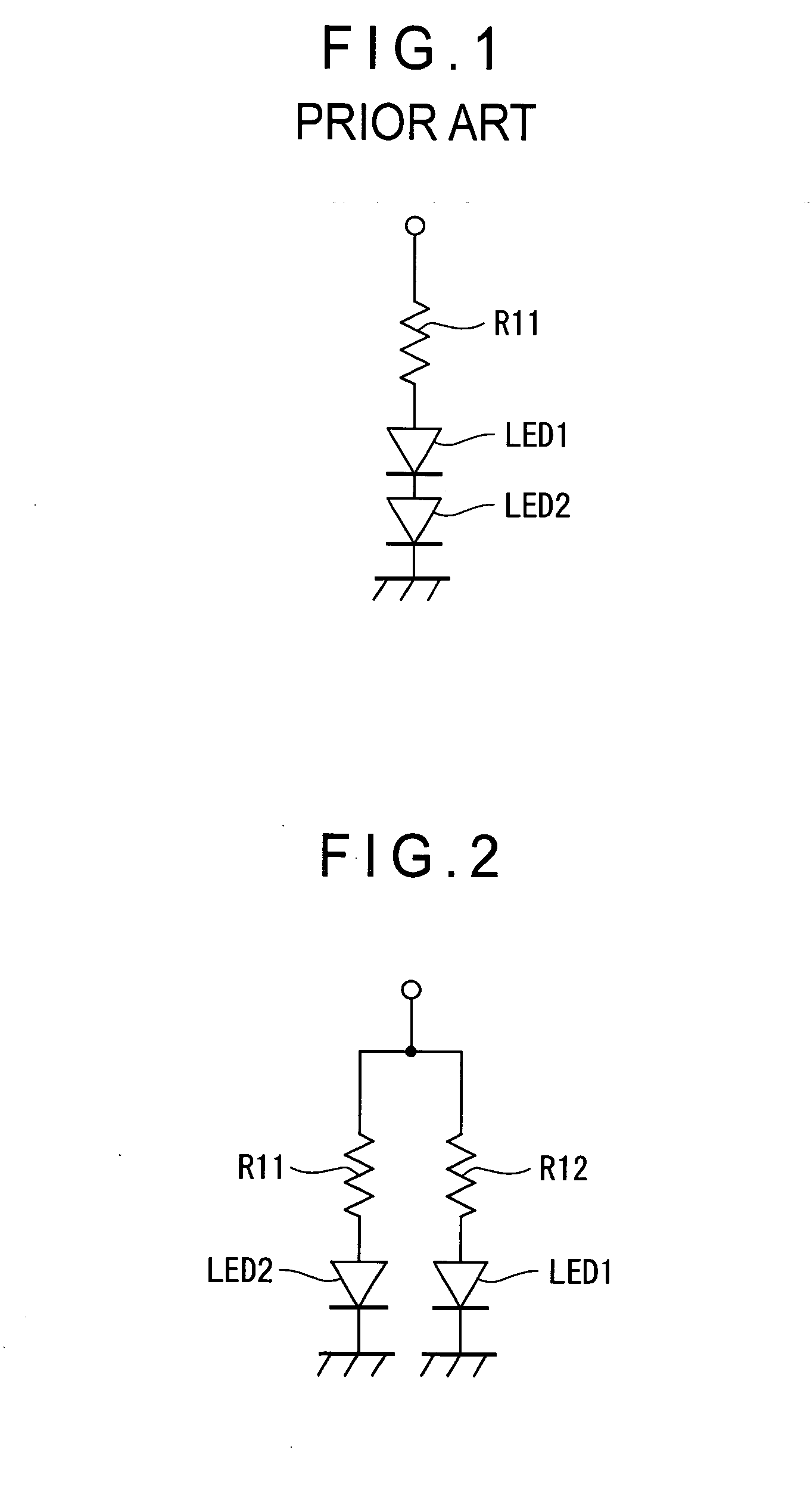
However, in the circuit configuration shown in FIG. 2, a plurality of serial circuits in which the resistors R12 and R13 for setting the luminance levels of the LEDs 1 and 2 are serially connected to the LEDs 1 and 2, respectively are connected in parallel, which increases the size and complexity of the circuit configuration more than that shown in FIG. 1.
Therefore, a constant-current circuit must be provided, which may complicate the device configuration.
As described above, the conventional lighting system that allows a plurality of light-emitting diodes LED 1 and LED 2 to light up has a problem that the size and complexity of the circuit configuration that allows a plurality of light-emitting diodes LED 1 and LED 2 to light up at different luminance levels and prevents the timings for the LEDs 1 and 2 to go off from being varied may be increased.

Method used


Image

  • Lighting device and lighting system
  • Lighting device and lighting system
  • Lighting device and lighting system

Examples


Embodiment Construction

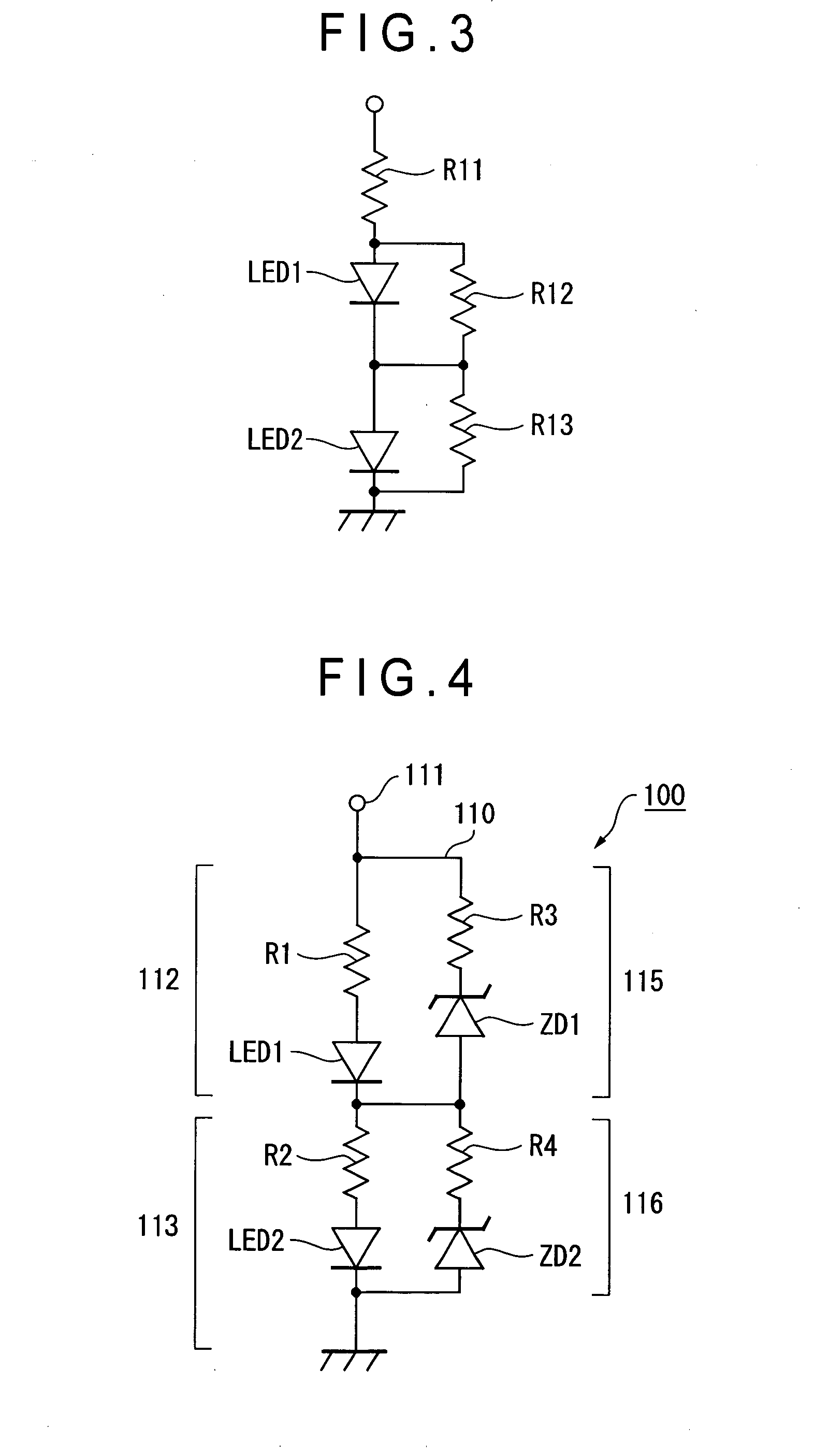
[0021] Embodiments of the present invention will be described below with reference to the accompanying drawings. In the following embodiments, a light-emitting diode (LED) is used as a light source. The light source used in the present invention is not limited to the LED, and any light emitting object including, for example, a lamp such as an electric bulb can be applied. FIG. 4 is a circuit diagram schematically showing a configuration of a lighting system according to the present invention.

(Configuration of Lighting System)

[0022] In FIG. 4, a reference numeral 100 denotes a lighting system. The lighting system 100 is used as an illumination necessary for button switches or knobs for setting operations of a car-mounted audio device or air-conditioner, or used as a backlight of a display device such as a liquid crystal panel that displays operation items or setting items. The lighting system 100 includes a plurality of (for example, two) light-emitting diodes LED 1 and LED 2 serv...


PUM


Abstract

First resistors (R1, R2) for setting a forward current value are connected in series to light-emitting diodes (LED 1, LED 2) respectively to constitute first serial circuits (112, 113), which are connected to an input terminal (111). Second serial circuits (115, 116) are connected in parallel to the first serial circuits (112, 113) respectively. The second serial circuits (115, 116) are constituted by a combination of a Zener diode (ZD1) and a second resistor (R3), and another combination of a Zener diode (ZD2) and a second resistor (R4). When a higher voltage than rated voltages of the light-emitting diodes (LED 1, LED 2) is applied, the Zener diodes (ZD1, ZD2) shunt current into the second serial circuit (115, 116) to allow the light-emitting diodes (LED 1, LED 2) to light up at desirable luminance levels different from each other. When a supplied power voltage decreases, current is not shunted, so that the same forward current flows through the light-emitting diodes (LED 1, LED 2), allowing the light-emitting diodes (LED 1, LED 2) to go off at the same timing.

Description

BACKGROUND OF THE INVENTION [0001] 1. Field of the Invention [0002] The present invention relates to a lighting device and a lighting system that allows a plurality of light sources to light up at different luminance levels from each other. [0003] 2. Description of Related Art [0004] A plurality of button switches for operation setup have been provided on electric equipments such as a car-mounted audio device or air-conditioner. In order to recognize the button switches even in the dark, a lighting system having a plurality of light-emitting diodes (LEDs) functioning as light sources in a lighting device has been widely used. Also in a small-sized liquid crystal display device used for, especially, a mobile phone, a lighting system provided with a plurality of LEDs acting as a backlight is in widespread use. [0005] As a circuit configuration of a lighting device that allows the plurality of LEDs to light up, the circuit configuration as shown in, for example, FIG. 1, in which light-...

Claims


Application Information

Patent Timeline
IPC IPC(8): H05B37/02H01L33/00H05B44/00
CPCH05B33/089H05B33/0821H05B45/40H05B45/54
Inventor INOUE, TAKAO
Owner PIONEER CORP
Learn More