
Handheld electronic device cradle with enhanced heat-dissipating capability

a handheld electronic device and cradle technology, applied in the direction of power cables, cables, instruments, etc., can solve the problems of increasing the temperature of the smart phone, the inability of the smart phone to function normally, and the inability to effectively remove the heat generated by the handheld electronic device from the devi

Active Publication Date: 2005-08-04
HTC CORP
View PDF12 Cites 19 Cited by
  • Summary
  • Abstract
  • Description
  • Claims
  • Application Information

AI Technical Summary

Benefits of technology

[0008] Accordingly, an objective of the present invention is to provide a cradle for a handheld electronic device. The cradle can generate forced heat-dissipating air flow to cool down the temperature of the handheld electronic device mounted on the cradle for charging the battery of the device.
[0009] It is still an objective of the present invention to provide a cradle for a handheld electronic device. The cradle can generate an air flow flowing from an interior of the handheld electronic device to an interior of the cradle to thereby take away heat generated by the device when it is mounted on the cradle for charging the battery of the device.
[0011] To achieve these and other objectives and in accordance with the purpose of the invention, as embodied and broadly described herein, the invention provides a cradle for a handheld electronic device. The cradle provides electrical power to the handheld electronic device and connects the handheld electronic device to a host computer so that the handheld electronic device can exchange data with the host computer. The cradle also provides a forced air circulation to carry heat away from the handheld electronic device inserted in the cradle, thereby to prevent the handheld electronic device from overheating.
[0012] In a first embodiment, the handheld electronic device has a first connection port. The cradle mainly comprises a casing, a second connection port and an electrical fan. The casing has an insertion slot. The second connection port is set up in the insertion slot of the casing for engaging with the first connection port of the handheld electronic device. The electrical fan is set up within the casing and is electrically connected to a power supply. The electrical fan is an axial fan. The casing has at least a ventilation slot that permits air inside the casing to leave therefrom. The cradle further includes a sealing element and a third connection port. The sealing element is set up inside the casing around the second connection port for fittingly engaging a bottom of the handheld electronic device. The third connection port is set up on the casing for electrically connecting with the power supply. Furthermore, the third connection port is electrically connected with the second connection port and can charge a spare rechargeable battery. The cradle further comprises a data exchange module. The data exchange module is set up inside the casing and electrically coupled to the second connection port. The data exchange module connects with a host computer through an electrical cable extending from the cradle so that the handheld electronic device can exchange data with the host computer. In this embodiment, the bottom of the handheld electronic device has a heat-dissipating opening. The handheld electronic device further comprises a valve. The valve is a movable component capable of closing the heat-dissipating opening. When not inserted into the cradle, the valve closes the opening. When inserted into the cradle, the valve is activated the leave the opening so that the opening is opened to an interior of the cradle. The electrical fan is activated to generate an air flow following from an interior of the handheld electronic device to enter the interior of the cradle via the heat-dissipating opening. Then, the air flow flows out of the cradle via the ventilation slot provided in the casing of the cradle. Thus, heat generated by the handheld electronic device during insertion in the cradle can be effectively dissipated.
[0013] In a second embodiment of the present invention, the cradle has an outer casing having an air inlet, an air outlet and an insertion slot. A fan-mounting seat is set up inside the outer casing and a blower type electrical fan is fastened to the fan-mounting seat. The cradle further comprises a cable for connecting with a host computer. When the handheld electronic device is plugged into the insertion slot, the cradle provides power to charge a rechargeable battery inside the handheld electronic device. Furthermore, the cradle provides a connection for exchanging data between the handheld electronic device and the host computer. Meanwhile, the electrical fan is activated to draw air into the cradle through the air inlet. The air entering the cradle is then blown out of the cradle through the air outlet and finally impinges at a region of an outer surface of the handheld electronic device where the battery of the handheld electronic device neighbors so that most of the heat produced by the device during its insertion in the cradle can be effectively carried away.

Problems solved by technology

Sometimes, the temperature increased may exceed the rated temperature limitation of the smart phone.
When this happens, the smart phone is not able to function normally.
Moreover, the temperature increased may cause the battery to overheat, which could lead to a disastrous explosion.
Therefore, how to effectively remove heat generated by the handheld electronic device from the device when it is put on the cradle for charging its battery becomes an issue to handheld electronic device manufacturers.

Method used


Image

  • Handheld electronic device cradle with enhanced heat-dissipating capability
  • Handheld electronic device cradle with enhanced heat-dissipating capability
  • Handheld electronic device cradle with enhanced heat-dissipating capability

Examples


Embodiment Construction

[0022] Reference will now be made in detail to the present preferred embodiments of the invention, examples of which are illustrated in the accompanying drawings. Wherever possible, the same reference numbers are used in the drawings and the description to refer to the same or like parts.

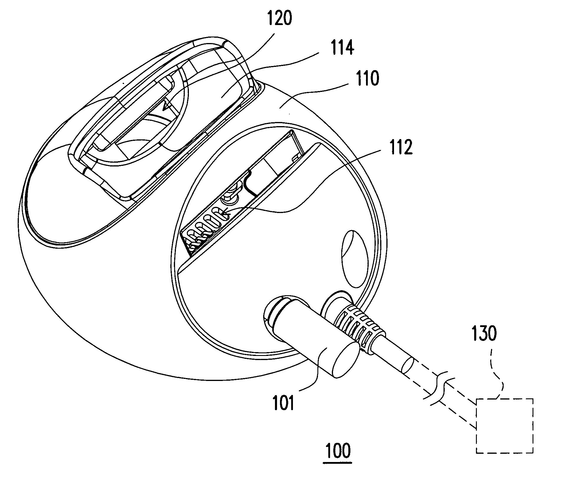
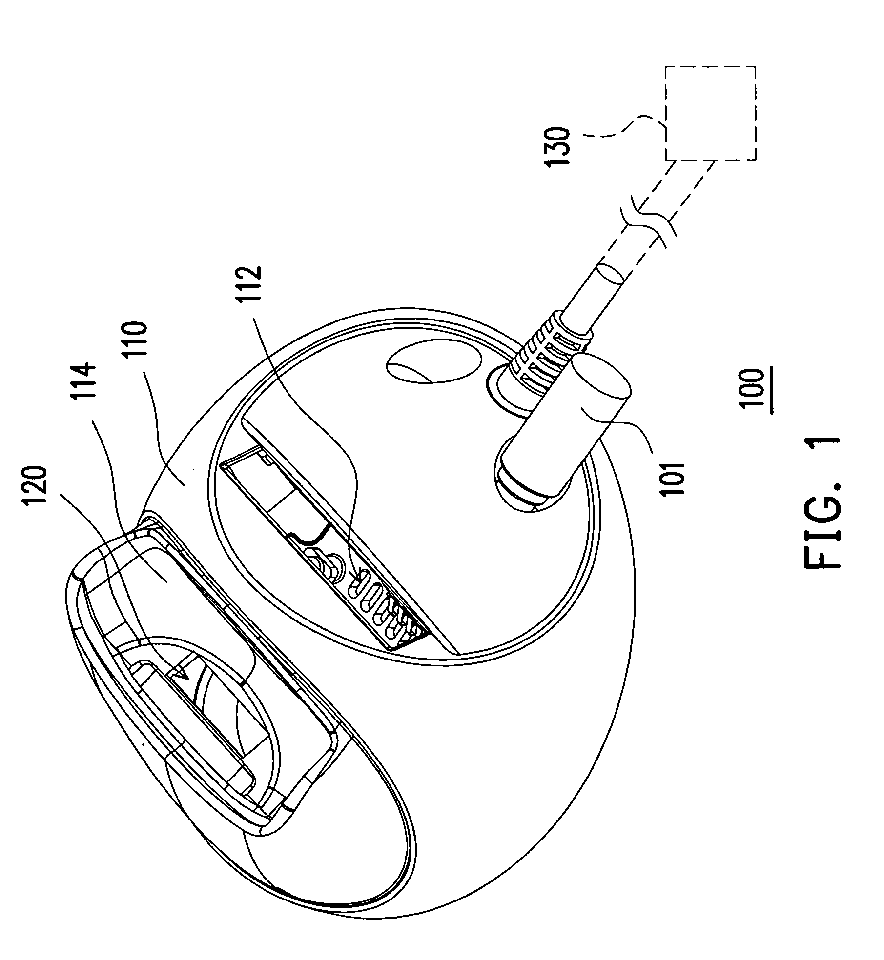
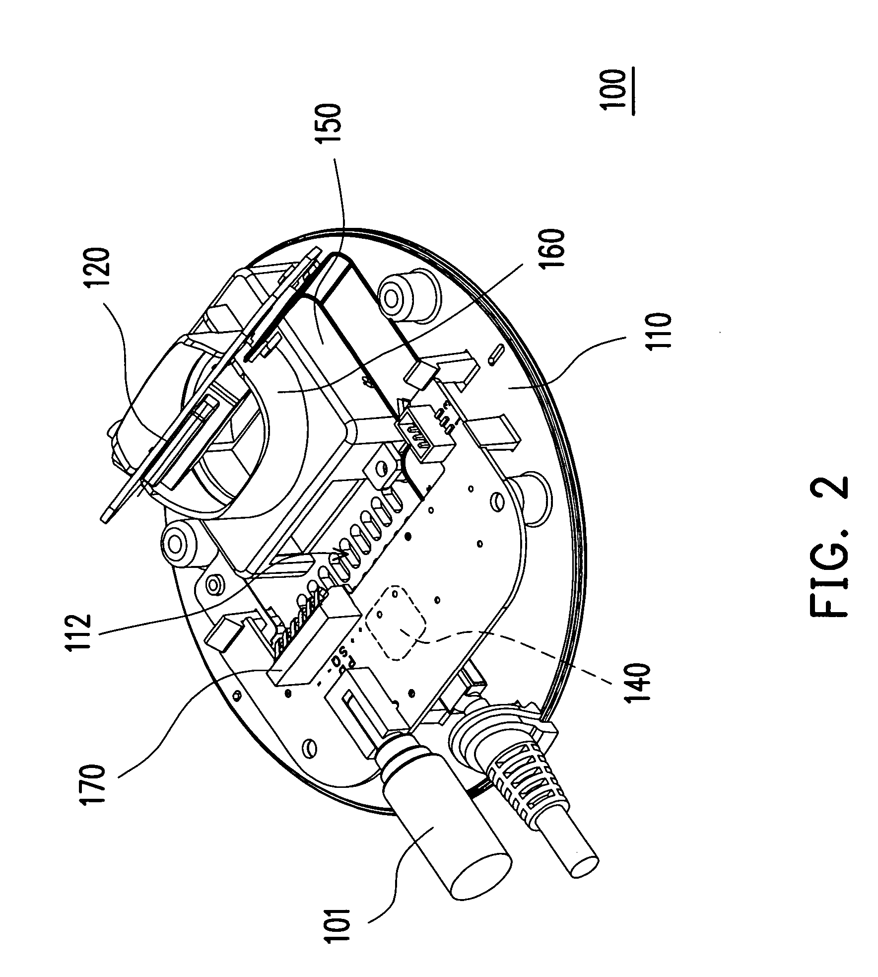
[0023]FIG. 1 is a perspective view showing a cradle 100 for handheld electronic device according to a first preferred embodiment of the present invention. FIG. 2 is a perspective view showing that a casing 110 of the cradle 100 of FIG. 1 is removed so that an interior of the cradle 100 can be seen. FIG. 3 is a perspective view of a handheld electronic device 200 for use with the cradle 100. As shown in FIGS. 1 through 3, the cradle 100 mainly comprises the casing 110, a second connection port 120 and an electrical fan 150. In this embodiment, the cradle 100 provides electrical power to a handheld electronic device 200 for charging a battery (not shown) inside the handheld electronic device 200 and ...


PUM


Abstract

A handheld electronic device cradle (300) with heat-dissipating capability is provided. The cradle is used for charging a build-in battery in a handheld electronic device (380) and connecting the handheld electronic device to a host computer so that the handheld electronic device can exchange information with the host computer. The cradle comprises a casing (310), a fan-mounting seat (350) set up in the casing, an electrical fan (351) secured to the seat and a cable (314) for connecting the cradle with the host computer. An insertion slot (311) is provided in the casing. When the handheld electronic device is inserted into the insertion slot, the cradle charges the battery in the handheld electronic device and connects the handheld electronic device with the host computer. Furthermore, the handheld electronic device can communicate with other devices through a wireless network. Heat produced by the handheld electronic device during its insertion in the cradle can be removed by the fan, which generates an air flow blowing on a hot region of the handheld electronic device to take heat away therefrom.

Description

CROSS-REFERENCE TO RELATED APPLICATION [0001] This application claims the priority benefit of Taiwan application serial no. 93201433, filed on Feb. 2, 2004. BACKGROUND OF THE INVENTION [0002] 1. Field of the Invention [0003] The present invention relates to a cradle for a handheld electronic device. More particularly, the present invention relates to a handheld electronic device cradle with enhanced heat-dissipating capability. [0004] 2. Description of the Related Art [0005] In this information conscious society, our reliance on electronic products increases every day. Following our need for a higher communicating speed, better performance, a lighter device and a compact design, a variety of handheld electronic devices are out in the market. At present, the most common handheld electronic devices include cellular phones, smart phones and personal digital assistants (PDAs). Through these handheld electronic devices, communication is no longer restricted to the office. In fact, people...

Claims


Application Information

Patent Timeline
Patent Type & Authority Applications(United States)
IPC IPC(8): G06F1/16G06F1/20H02J7/00
CPCG06F1/1632H02J7/0044G06F1/20
Inventor LEE, JENSENCHEN, YILITSAI, CHIL-WEI
Owner HTC CORP
Learn More