Heat-dissipating device having air-guiding cover

a technology of heat dissipation device and air guide cover, which is applied in the direction of cooling/ventilation/heating modification, semiconductor device details, semiconductor/solid-state device details, etc., can solve the problems of increasing the heat generated, electronic elements may not be operated normally, and the power consumed by electronic devices also becomes large, so as to improve the heat dissipation effect, and enhance the effect of air

Inactive Publication Date: 2009-06-18
GOLDEN SUN NEWS TECHN +1
View PDF16 Cites 5 Cited by
  • Summary
  • Abstract
  • Description
  • Claims
  • Application Information

AI Technical Summary

Benefits of technology

[0006]The present invention is to provide a heat-dissipating device having an air-guiding cover. Via an air-guiding blade of the air-guiding cover, the air blown by a fan can be guided in or out of a heat-dissipating body rapidly. As a result, the air can be enhanced to a larger extent, so that the air can take away the heat on the heat-dissipating pieces rapidly to improve the heat-dissipating effect.

Problems solved by technology

Recently, since the operation speed of electronic elements in an electronic device becomes much faster, the power consumed by the electronic device also becomes larger, which increases the heat generated to a large extent.
If the heat is not removed immediately, the electronic elements may not be operated normally.
However, such a heat-dissipating action through the use of heat conduction has been unable to deal with the current electronic element that generates a large amount of heat, another conventional heat-dissipating device is thus developed, such as that disclosed in Taiwan Patent Publication No.
Unfortunately, turbulence is generated in the interior of the heat-dissipating body 10c to hinder the air from flowing out of the heat-dissipating body, which results in a bad heat-dissipating effect.

Method used


Image

  • Heat-dissipating device having air-guiding cover
  • Heat-dissipating device having air-guiding cover
  • Heat-dissipating device having air-guiding cover

Examples


Embodiment Construction

[0018]The detailed description and the technical contents of the present invention will be explained with reference to the accompanying drawings. However, the drawings are illustrative only and are not used to limit the scope of the present invention.

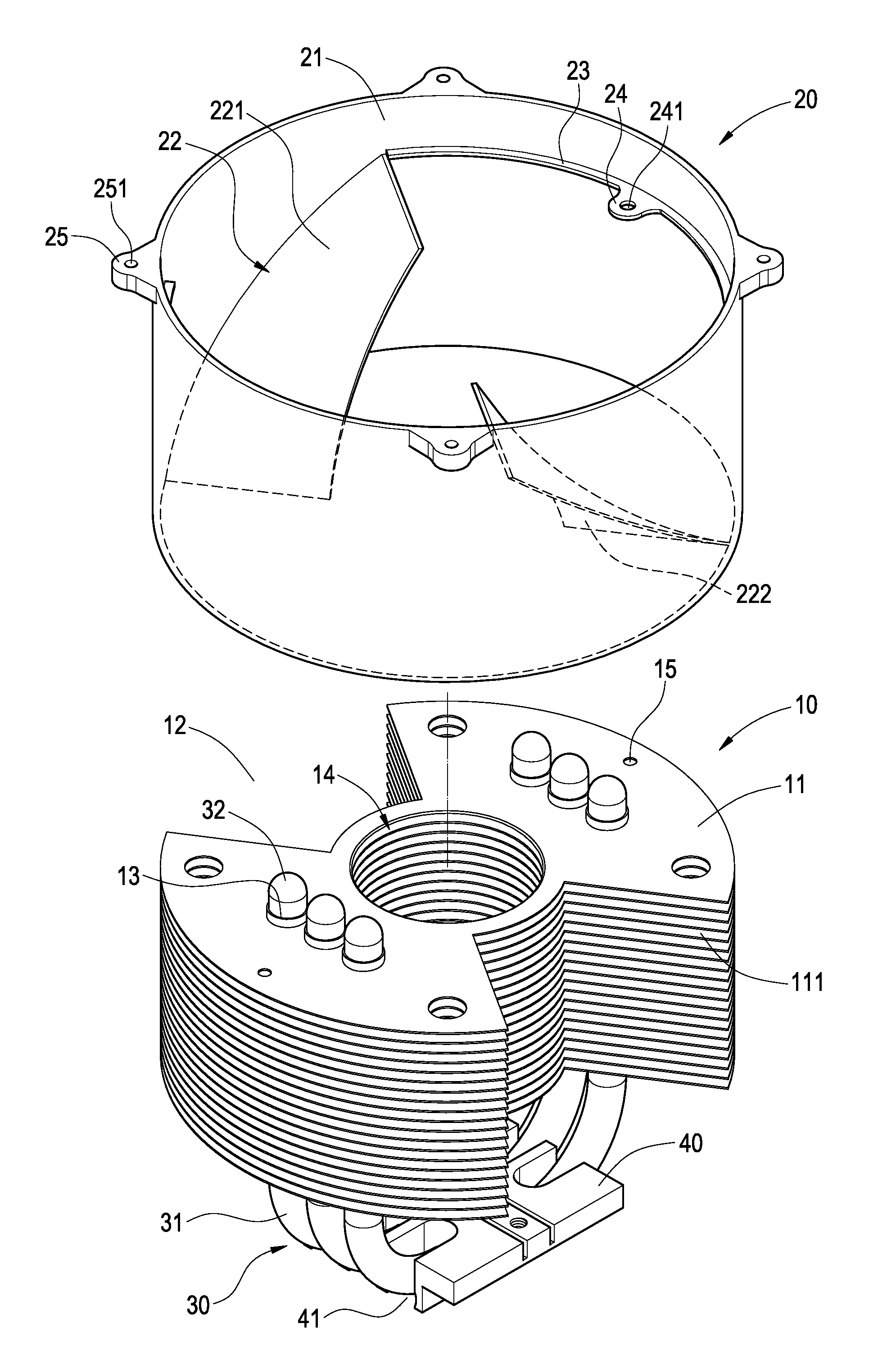
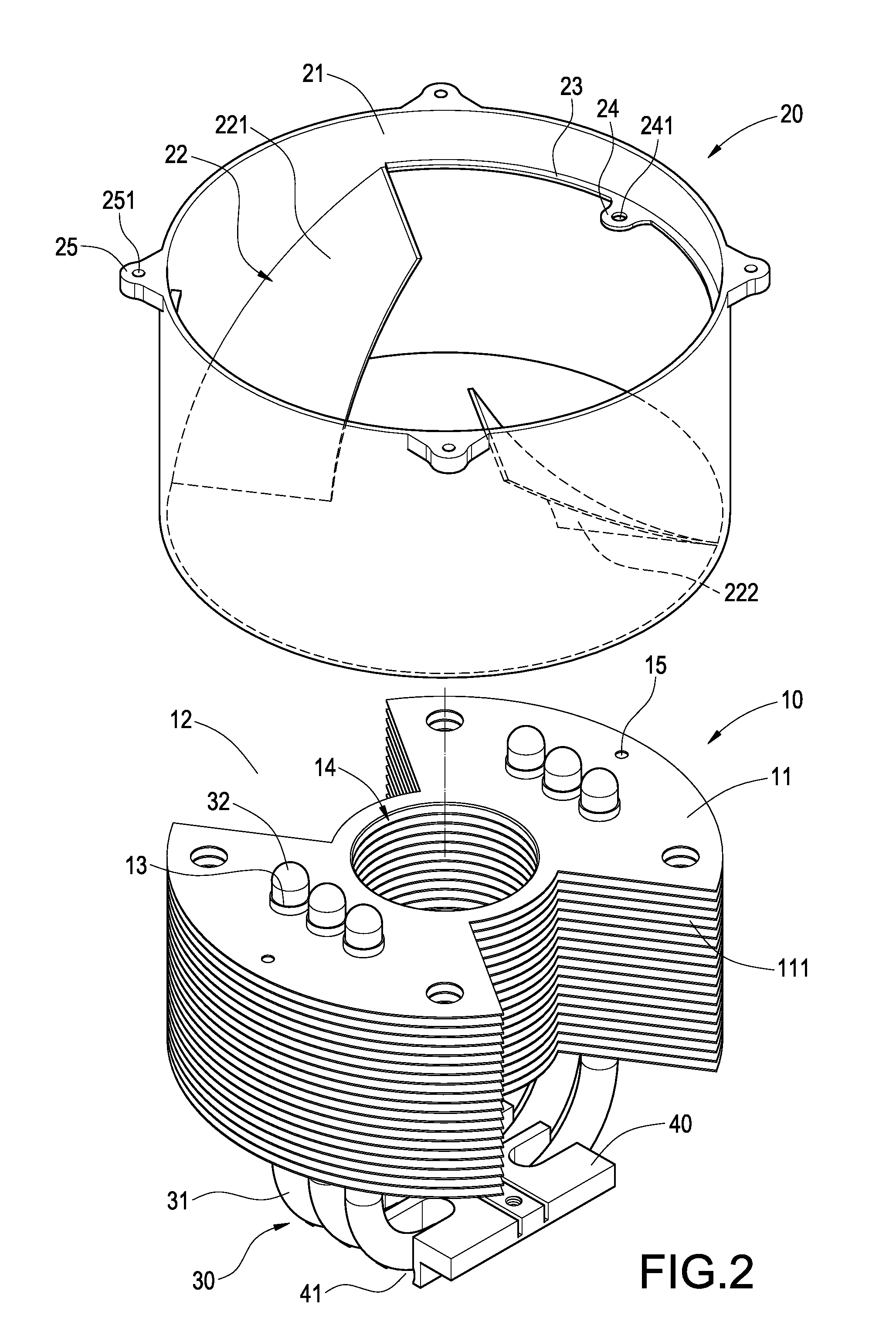
[0019]FIG. 2 is an exploded perspective view showing the structure of the present invention. FIG. 3 is an exploded perspective view showing the structure in FIG. 2 and a fan. FIG. 4 is a bottom perspective view of the present invention. The present invention provides a heat-dissipating device having an air-guiding cover, which can be arranged on a heat-generating electronic element of a main board (not shown) and includes a heat-dissipating body 10, an air-guiding cover 20, a plurality of heat pipes 30, a fixing base 40 and a fan 50. The heat-dissipating body 10 is constituted of a plurality of heat-dissipating pieces 11 that are stacked up at intervals. On the heat-dissipating body 10, venting channels 12 penetrating through each heat-...


PUM


Abstract

A heat-dissipating device having an air-guiding cover includes a heat-dissipating body, an air-guiding cover, a plurality of heat pipes, a fixing base and a fan. The heat-dissipating body is constituted of a plurality of heat-dissipating pieces that are stacked up at intervals. On the heat-dissipating body, venting channels and a plurality of through holes are provided. The air-guiding cover includes a hollow cylinder and an air-guiding blade. The hollow cylinder covers the heat-dissipating body. The air-guiding blade is accommodated in the venting channel. Each of the plurality of heat pipes includes a section to be heated and a heat-releasing section extending from the section to be heated. The heat-releasing section penetrates into the through hole. The bottom of the fixing base is provided with a plurality of grooves for accommodating the sections to be heated of the heat pipes. The fan is provided above the air-guiding cover. Via the above arrangement, the air-guiding cover guides the airflow blown by the fan, thereby enhancing the heat-dissipating effect.

Description

BACKGROUND OF THE INVENTION[0001]1. Field of the Invention[0002]The present invention relates to a heat-dissipating device, and in particular to a heat-dissipating device having an air-guiding cover.[0003]2. Description of Prior Art[0004]Recently, since the operation speed of electronic elements in an electronic device becomes much faster, the power consumed by the electronic device also becomes larger, which increases the heat generated to a large extent. If the heat is not removed immediately, the electronic elements may not be operated normally. In order to make the electronic elements to be operated in normal temperature, it is necessary to provide a heat-dissipating device to dissipate the heat.[0005]A traditional heat-dissipating device dissipates the heat generated by a heat-generating electronic element by means of adhering a heat-dissipating body on a surface of the heat-generating electronic element via heat-conducting paste. However, such a heat-dissipating action through...

Claims


Application Information

Patent Timeline
Patent Type & Authority Applications(United States)
IPC IPC(8): H05K7/20
CPCH01L23/427H01L23/467H01L2924/0002H01L2924/00
Inventor HSU, KENCHENG, CHIH-HUNGLIN, KUO-LEN
Owner GOLDEN SUN NEWS TECHN
Why Eureka
Try Eureka