
Cap and droplet discharge apparatus

a technology of droplet and discharge apparatus, which is applied in printing and other directions, can solve the problems of not exerting an influence on discharge operation, and drying of ink, and achieves the effects of improving the discharge performance of the head, increasing manufacturing costs, and increasing the number of components

Inactive Publication Date: 2005-08-04
BROTHER KOGYO KK
View PDF2 Cites 4 Cited by
  • Summary
  • Abstract
  • Description
  • Claims
  • Application Information

AI Technical Summary

Benefits of technology

[0005] While a cap of the former type that directly seals an opening of a nozzle is highly effective to prevent drying of ink, there is a possibility that direct sealing of the opening of the nozzle with the cap may exert an influence on discharge operation immediately after the cap is detached.
[0006] In contrast, a cap of the latter type forming a sealed space on the surface formed with the opening of the nozzle presents a possibility of causing drying of ink when left for a long time due to the sealed space having a certain volume defined on the surface formed with the opening of the nozzle. However, the cap of the latter type, which does not at all contact the surface formed with the opening of the nozzle, will not exert an influence on discharge operation when left for a short time.
[0007] Accordingly, by using caps of the two types appropriately depending on the standby state of a head (e.g. the length of the standby time), an improved discharge performance of the head may be achieved.

Problems solved by technology

In contrast, a cap of the latter type forming a sealed space on the surface formed with the opening of the nozzle presents a possibility of causing drying of ink when left for a long time due to the sealed space having a certain volume defined on the surface formed with the opening of the nozzle.
However, the cap of the latter type, which does not at all contact the surface formed with the opening of the nozzle, will not exert an influence on discharge operation when left for a short time.
However, providing both caps of the two types, as disclosed in the Publication of Japanese Unexamined Patent Application No. 2002-103594, will lead to an increased number of components, thereby to an increased manufacturing cost of a droplet discharge apparatus, and to an increase in size of the droplet discharge apparatus.

Method used


Image

  • Cap and droplet discharge apparatus
  • Cap and droplet discharge apparatus
  • Cap and droplet discharge apparatus

Examples


Embodiment Construction

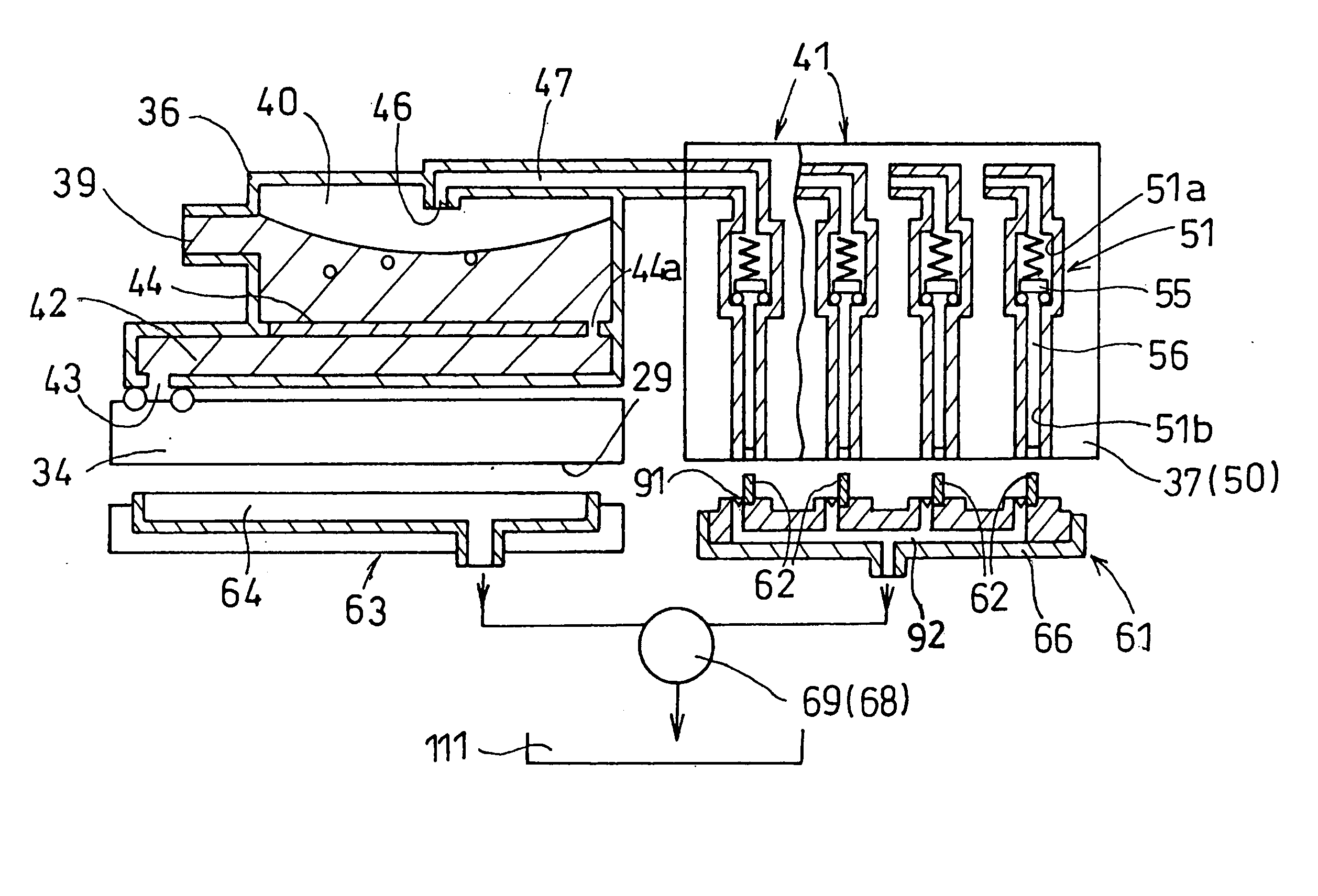
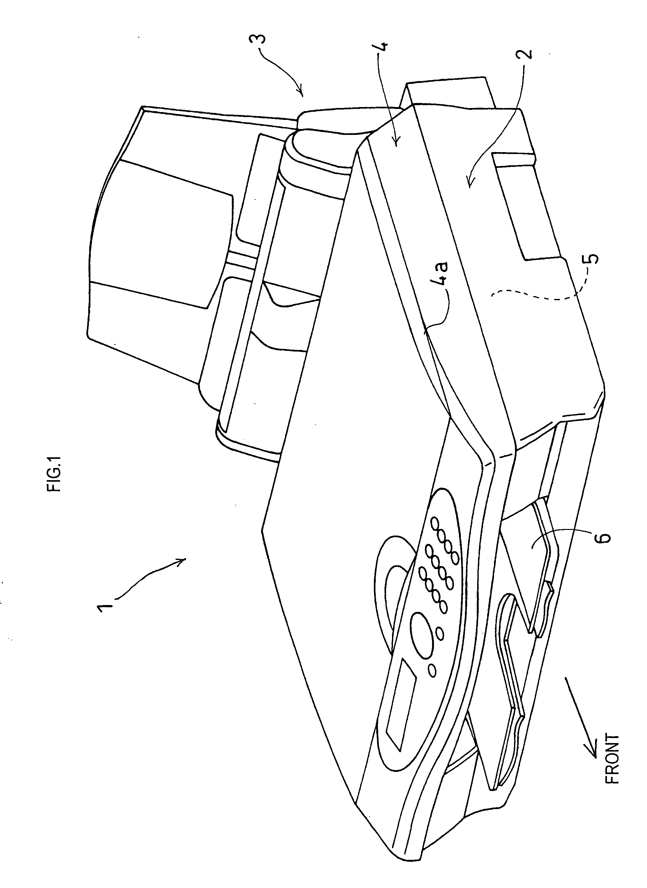
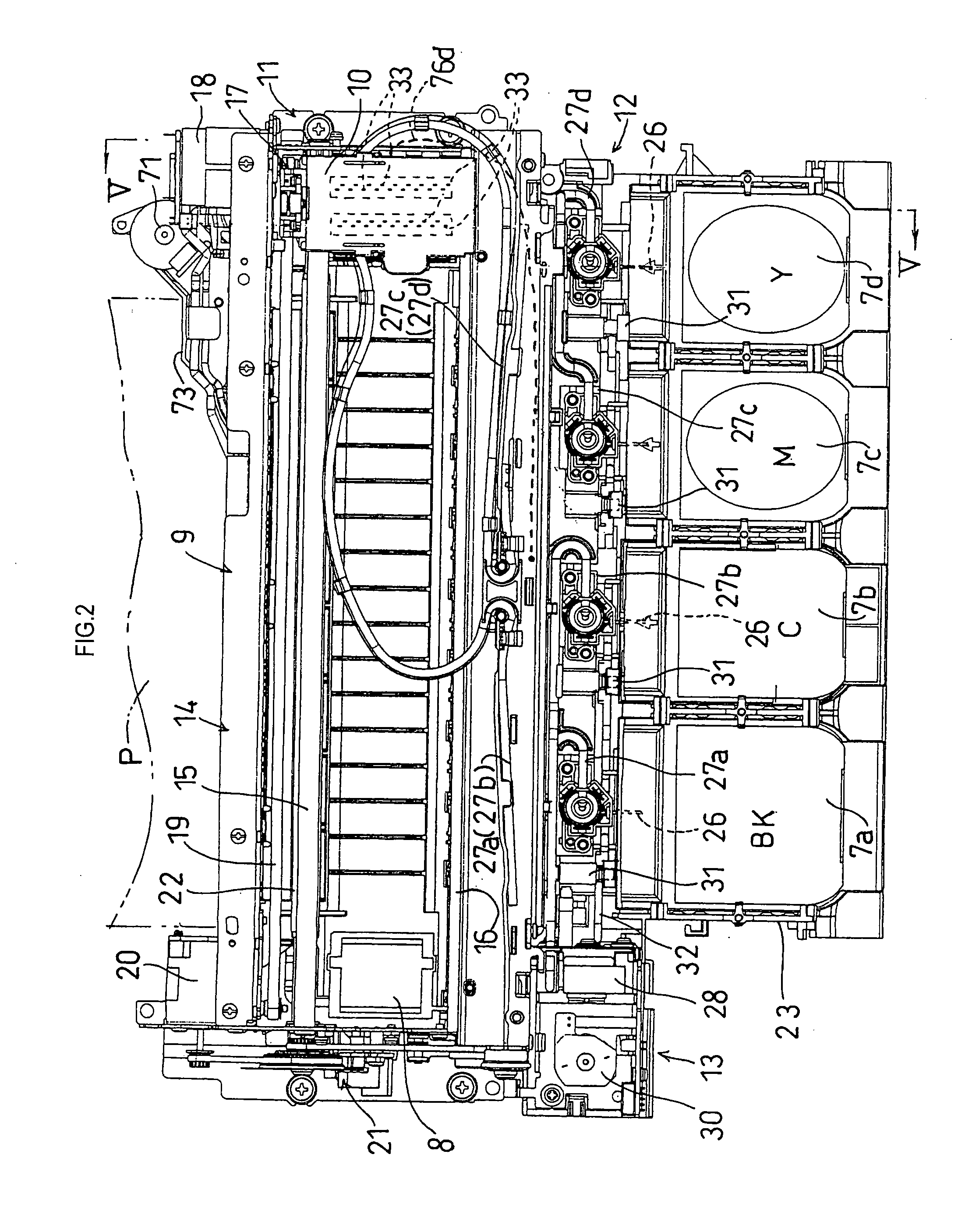
[0052] In the present embodiment, the present invention is applied to a multi-function apparatus (MFC: Multi-Function Center) 1 equipped with a printer function, a copier function, a scanner function and a facsimile function. As shown in FIG. 1, a paper feeder 3 is provided at a rear end of a main housing 2 of the apparatus, and a document reading unit 4 for the copier function and the facsimile function is provided on an upper side in front of the paper feeder 3. An inkjet printer 5 (to be hereinafter described) for serving the printer function is provided under the entire lower surface of the document reading unit 4. A paper exit tray 6 for receiving recording media, such as a sheet of paper P (not shown) to be discharged after recording (printing), is provided in front of the inkjet printer 5.

[0053] The document reading unit 4 is designed, although not-shown, to be pivotable up and down around a horizontal shaft at its rear sad portion. When a cover 4a is opened upward, there is...


PUM


Abstract

A cap capable of sealing a nozzle by two methods and a droplet discharge apparatus using the cap. When the cap is pressed onto a nozzle surface with the nozzle aligned with a center of a covering portion, a lip continuously contacts the surrounding of an opening of the nozzle, thereby forming a sealed space on the surface formed with the opening of the nozzle. Although ink in the nozzle may dry when left for a long time, no influence on ink discharge operation immediately after the cap is detached is expected since the cap does not directly seal the opening. When the cap is pressed onto the nozzle surface with the nozzle aligned with a center of a sealing portion, the substantially flat sealing portion seals the opening, thereby effectively preventing drying of ink, although there may be an influence on discharge operation immediately after the cap is detached.

Description

BACKGROUND OF THE INVENTION [0001] (i) Field of the Invention [0002] The present invention relates to a cap for sealing a nozzle for discharging droplets and a droplet discharge apparatus provided with a head capable of selectively discharging droplets from the nozzle as well as the cap. [0003] (ii) Background Art [0004] A known example of a conventional droplet discharge apparatus of this type is a so-called on-demand-type inkjet printer provided with a head capable of selectively discharging ink in droplets from a nozzle. In such an inkjet printer, the nozzle is sealed with a cap to prevent the ink in the nozzle from drying or becoming solidified during a standby time when the ink is not discharged. There are known caps, such as a cap of one type that directly seals an opening of a nozzle, and a cap of another type that has a lip closely contacting a circumference of an opening of a nozzle continuously and forms a sealed space on the surface formed with the opening of the nozzle b...

Claims


Application Information

Patent Timeline
Patent Type & Authority Applications(United States)
IPC IPC(8): B41J2/165
CPCB41J2/16508
Inventor UMEDA, TAKAICHIRO
Owner BROTHER KOGYO KK
Learn More