
Medical instrument and method of use

a technology of medical instruments and methods, applied in the field of surgical instruments, can solve the problems of high “control” and achieve the effect of preventing desiccation, eschar, smoke and tissue sticking

Active Publication Date: 2012-10-25
TSUNAMI MEDTECH
View PDF0 Cites 36 Cited by
  • Summary
  • Abstract
  • Description
  • Claims
  • Application Information

AI Technical Summary

Benefits of technology

[0011] The instrument and method of the invention generate vapor phase media that is controllable as to volume and ejection pressure to provide a not-to-exceed temperature level that prevents desiccation, eschar, smoke and tissue sticking.

Problems solved by technology

While such prior art forms of energy delivery work well for some applications, Rf and laser energy typically cannot cause highly “controlled” and “localized” thermal effects that are desirable in microsurgeries or other precision surgeries.

Method used


Image

  • Medical instrument and method of use
  • Medical instrument and method of use
  • Medical instrument and method of use

Examples


embodiment 500

[0080]FIG. 21 illustrates another system embodiment 500 which includes components and features as in the embodiments of FIGS. 12-20 except that the configuration is adapted for the working end of a small diameter rigid probe or a flexible catheter. In FIG. 21, the interior chamber 510 comprises an elongate lumen of a member 512 having an insulated wall 514. A flow diffuser is located in a proximal portion of lumen 510 (not shown). In one embodiment, the interior of the lumen 510 comprises an NTCR surface indicated at 515. The NTCR surface 515 is coupled to insulated lead 518 and the Rf source 420 to thus comprise a series circuit. The NTCR surface 515 is capable of internal I2R heating to thereby cause heating and vaporization of media flows in the lumen. A conductive filament 520 is carried in lumen 510 with the filament having kinks or bends 522 so that the filament does not continuously contact the NTCR surface. The filament 520 is electrically conductive and is coupled to the Rf...

embodiment 600

[0082]FIG. 22-24 illustrate another probe embodiment 600 that is adapted for tissue ablation, tissue disintegration and tissue extraction. The probe has a handle portion and vapor source that is similar to any of the handle embodiments of FIGS. 7, 11, 12, and 14-20 for providing a flow of a vapor media. Probe 600 of FIG. 22 has electrical source 420, fluid inflow source 435A and controller 435B as described with reference to FIGS. 12 and 14-20. Probe 600 also has a negative pressure source 270 as described generally with reference to FIGS. 7 and 11 above.

[0083] The probe 600 of FIG. 22 has handle portion 602 that transitions to extension member 605 having axis 608 that extends to working end 610. The probe 600 has a central aspiration lumen 615 extending through the probe body to an open distal termination. The probe has a vapor flow channel 620 for providing a flow of vapor to working end 610 that is configured as a concentric channel between first and second walls, 622 and 624 res...


PUM


Abstract

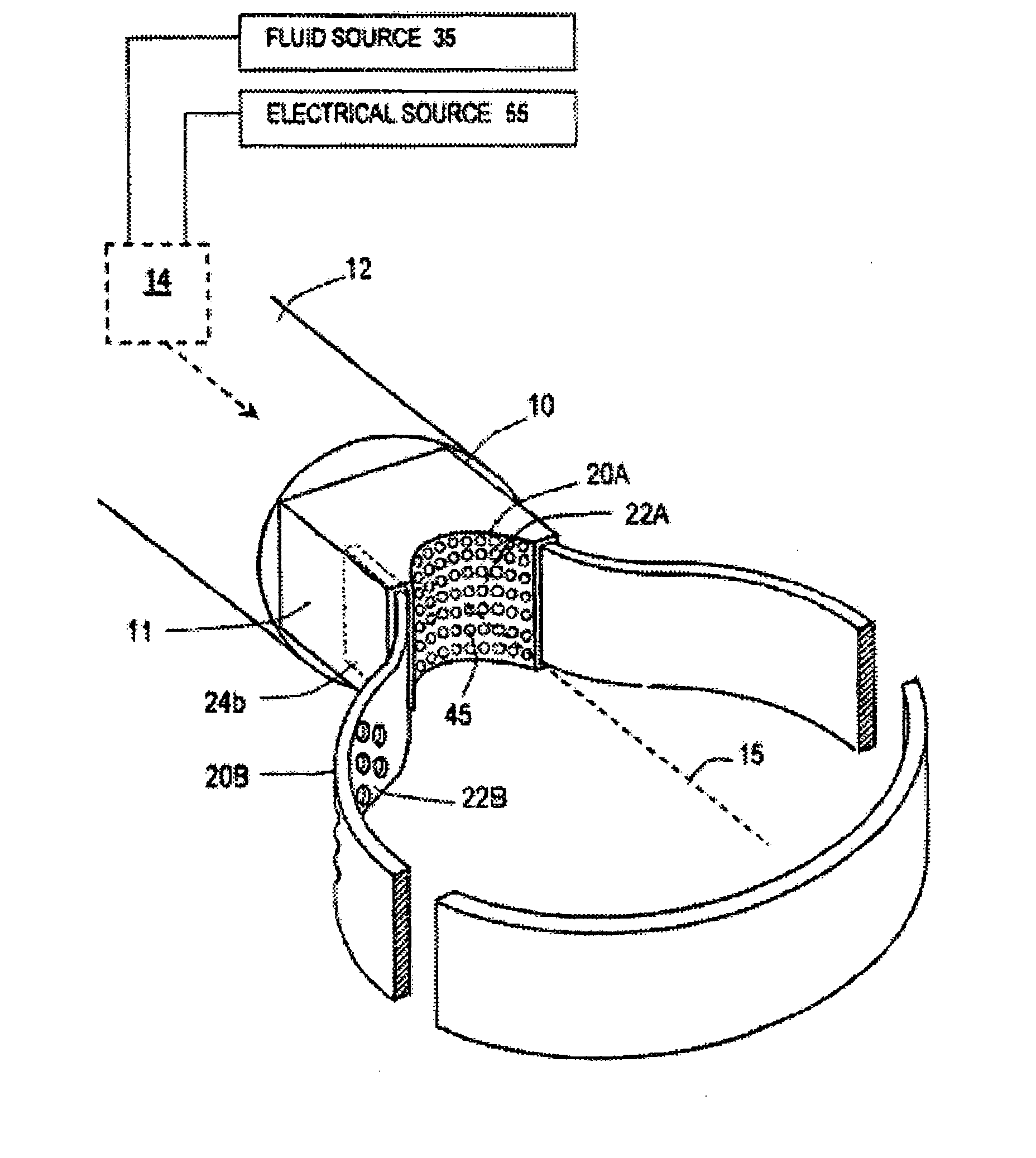
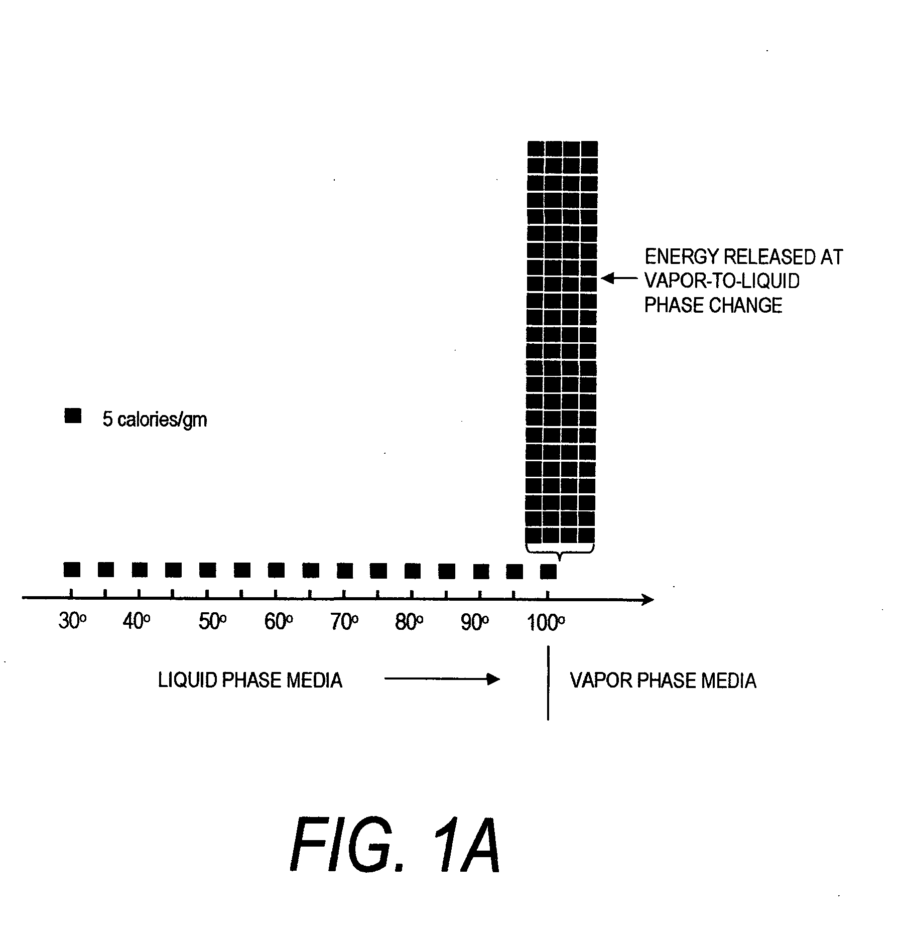
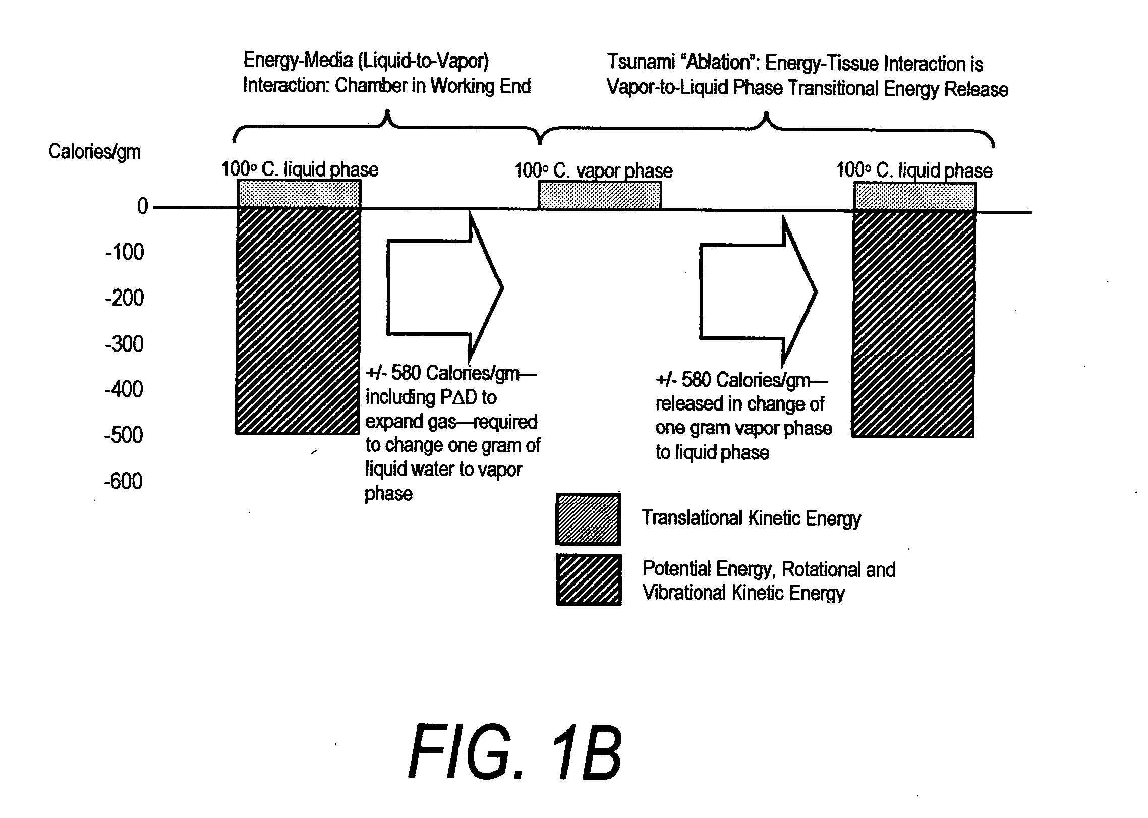
An instrument for thermally-mediated therapies in targeted tissue volumes or for volumetric removal of tissue. In one embodiment, the instrument has an interior chamber that includes a diffuser structure for diffusing a biocompatible conductive fluid that is introduced under high pressure. The interior chamber further includes surfaces of opposing polarity electrodes for vaporizing the small cross-section diffused fluid flows created within a diffuser structure. In one embodiment, the diffuser structure includes a negative temperature coefficient of resistance material between the opposing polarity surfaces. The NTCR structure can self-adjust the lengths of current paths between the opposing polarities to insure complete vaporization of the volume of flow of conductive fluid. The non-ionized vapor phase media is ejected from a working surface of the instrument and a controlled vapor-to-liquid phase change in an interface with tissue applies thermal energy substantially equal to the heat of vaporization to ablate tissue. In another embodiment, the instrument provides voltage means for converting the non-ionized vapor phase media into an ionized media or plasma for applying energy to body structure.

Description

CROSS-REFERENCE TO RELATED APPLICATIONS [0001] This application claims benefit of Provisional U.S. Patent Application Ser. No. 60 / 643,045 filed Jan. 11, 2005 titled Surgical Instrument and Method of Use. This application also is a continuation-in-part of co-pending U.S. application Ser. No. 10 / 681,625, filed Oct. 7, 2003 titled Medical Instruments and Techniques for Thermally-Mediated Therapies. This application also is a continuation-in-part of co-pending U.S. application Ser. No. 11 / 158,930 filed Jun. 22, 2005 titled Medical Instruments and Techniques for Treating Pulmonary Disorders. This application also is a continuation-in-part of co-pending U.S. application Ser. No. 11 / 244,329 filed Oct. 5, 2005 titled Medical Instrument and Method of Use. All of the above applications are incorporated herein by this reference and made a part of this specification, together with the specifications of all other commonly-invented applications cited in the above applications.FIELD OF THE INVENTI...

Claims


Application Information

Patent Timeline
Patent Type & Authority Applications(United States)
IPC IPC(8): A61B18/18A61F7/12A61F7/00
CPCA61B18/04A61B18/042A61B2018/048A61B2018/0063A61B2018/046A61B2018/00619
Inventor SHADDUCK, JOHN H.HOEY, MICHAEL
Owner TSUNAMI MEDTECH
Learn More