
Method and system for motion adaptive deinterlacer with integrated directional filter

a technology of directional filter and motion adaptive deinterlacer, which is applied in the direction of signal generator with optical-mechanical scanning, television system, brightness and chrominance signal processing circuit, etc., can solve the problems of video images containing a lot of motion, certain problems may arise concerning the motion of objects from image to image, and the motion of objects may be difficult to distinguish between images

Inactive Publication Date: 2005-08-04
AVAGO TECH INT SALES PTE LTD
View PDF9 Cites 21 Cited by
  • Summary
  • Abstract
  • Description
  • Claims
  • Application Information

AI Technical Summary

Benefits of technology

[0024] Determining the direction of the edge in the image comprises determining a gradient of the edge in a first direction, and determining a gradient of the edge in a second direction. The gradient in the first direction and the gradient in the second direction may be used to determine the angle of the edge, which may be used to determine the direction of the edge. The gradient in the first direction and the gradient in the second direction may also be used to determine the strength of the edge. The determined direction of the edge may then be used to select filter coefficients, which may be used to produce the spatial average of the edge in the interlaced video images. The filter coefficients may be programmable, thereby permitting at least one of a plurality of filter coefficients to be selected.

Problems solved by technology

In the field of video compression, communication, decompression, and display, there has been for many years problems associated with supporting both interlaced content and interlaced displays, along with progressive content and progressive displays.
Certain problems may arise concerning the motion of objects from image to image.
However, problems arise with video images containing a lot of motion and change from one image to another, when converted from interlaced to progressive format.
When motion is detected between fields, it may be very difficult to use temporal information for deinterlacing.
However, often the source material has diagonal lines, or curved edges, and using a spatial filter may not yield satisfactory results.

Method used


Image

  • Method and system for motion adaptive deinterlacer with integrated directional filter
  • Method and system for motion adaptive deinterlacer with integrated directional filter
  • Method and system for motion adaptive deinterlacer with integrated directional filter

Examples


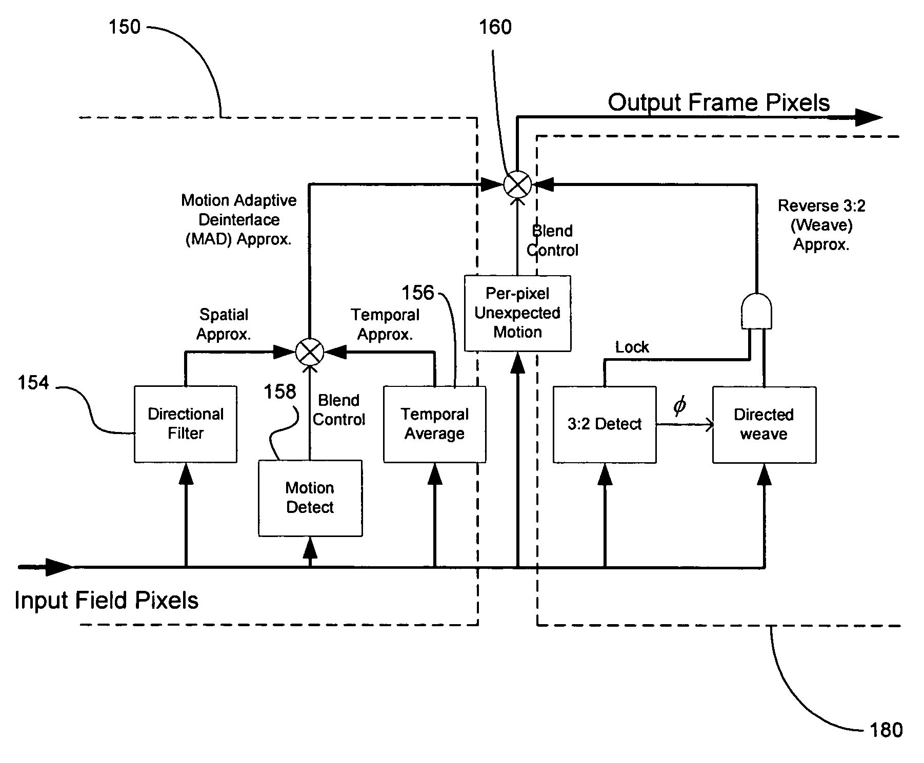
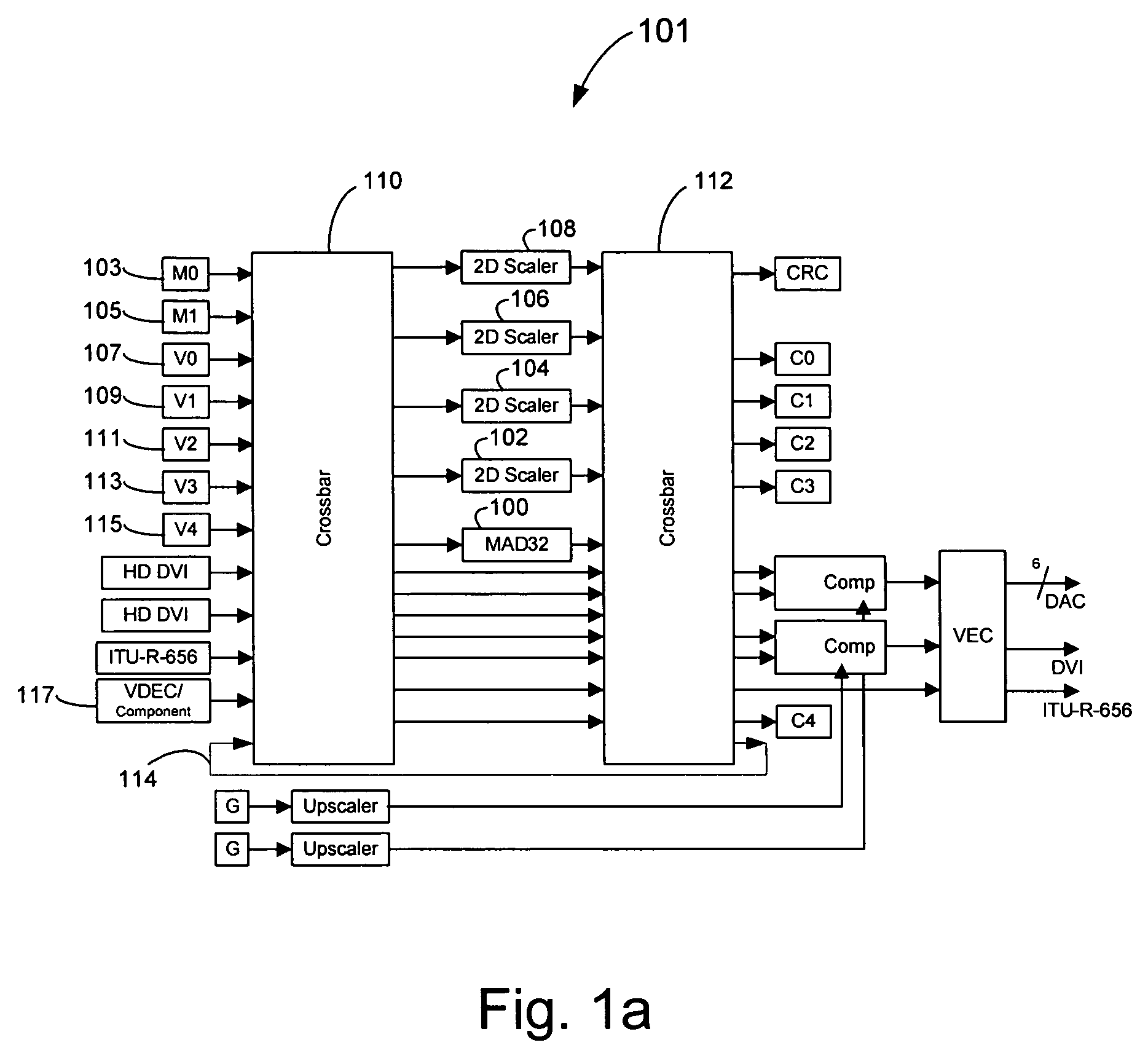
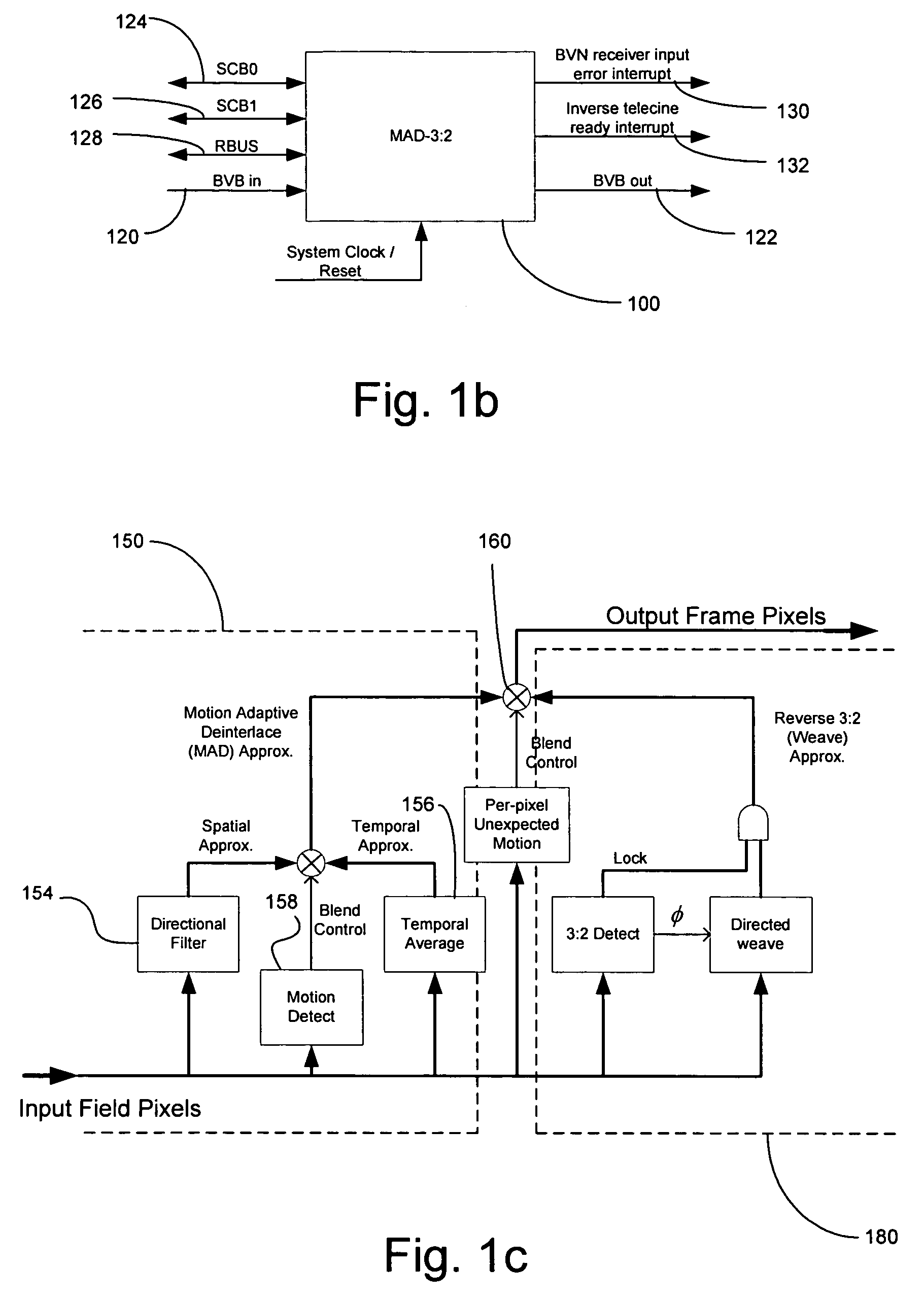
Embodiment Construction

[0033] Aspects of the present invention relate to processing of video signals. More specifically, certain embodiments of the invention relate to a method and system for a motion adaptive de-interlacer with an integrated directional filter.

[0034] Certain aspects of the invention may comprise methods and systems for a motion adaptive deinterlacer (MAD) capable of reverse 3:2 pull-down and 3:2 pull-down with cadence detection, which may be referred to as MAD-3:2 or MAD32, that may be utilized in a video network (VN). The algorithms and architectures for the motion adaptive deinterlacer may be adapted to acquire interlaced video fields from one of a plurality of video sources in the video network and convert the acquired interlaced video fields into progressive frames, at double the display rate, in a visually pleasing manner.

[0035] The motion adaptive deinterlacer (MAD-3:2) may be adapted to accept interlaced video input from a video bus (VB) and output deinterlaced, progressive vide...


PUM


Abstract

A system and method that produces a spatial average for interlaced video in a deinterlacer. The system detects edges in the video images and determines the angle at which the edges are oriented based on the gradient in the x-direction and the gradient in the y-direction. The direction of the edge is determined using the angle information of the edge. The system may also determine the strength of the edge. Based on the determined characteristics of the edge a filter may be selected to produce a spatial average of the edge in the image.

Description

RELATED APPLICATIONS [0001] This patent application makes reference to, claims priority to and claims benefit from U.S. Provisional Patent Application Ser. No. 60 / 540,826, entitled “Method and System for Motion Adaptive Deinterlacer with Integrated Directional Filter,” filed on Jan. 30, 2004, the complete subject matter of which is hereby incorporated herein by reference, in its entirety. [0002] This application makes reference to: [0003] U.S. patent application Ser. No. 10 / 314,525 filed Dec. 9, 2002; [0004] U.S. patent application Ser. No. ______ (Attorney Docket No. 15439US02) filed Sep. 21, 2004; [0005] U.S. patent application Ser. No. 10 / 875,422 (Attorney Docket No. 15443US02) filed Jun. 24, 2004; [0006] U.S. patent application Ser. No. ______ (Attorney Docket No. 15448US02) filed Sep. 21, 2004; [0007] U.S. patent application Ser. No. 10 / 871,758 (Attorney Docket No. 15449US02) filed Jun. 17, 2004; [0008] U.S. patent application Ser. No. ______ (Attorney Docket No. 15450US02) fil...

Claims


Application Information

Patent Timeline
Patent Type & Authority Applications(United States)
IPC IPC(8): H04N5/14H04N5/44H04N9/78
CPCH04N7/012H04N5/142
Inventor NEUMAN, DARRENLAW, PATRICK
Owner AVAGO TECH INT SALES PTE LTD
Learn More