
Projection-area dependent display/operating device

Inactive Publication Date: 2005-08-04
HEIDELBERGER DRUCKMASHINEN AG
View PDF33 Cites 35 Cited by
  • Summary
  • Abstract
  • Description
  • Claims
  • Application Information

AI Technical Summary

Benefits of technology

[0010] In accordance with another feature of the invention, the image is an operating interface. As such, it is possible for the projected image not only to replace the display device of a monitor but also to offer the full functionality of a touch screen display, that is to say, the operator can touch operating elements of the projected image with his fingers, as in the case of a touch screen, and can trigger corresponding functions. Therefore, the projected image serves as a fully adequate operating interface.
[0030] Provision can also be made for the projector and color-testing lamp to be combined in a projection lamp. In such a case, it is particularly advantageous if the latter only includes a projector that can both project an image and also emit monochromatic light for assessing the coloring of the printed sheet. The projector, as a projection lamp, then, also performs concomitantly the function of the color-testing lamp. Such a function can be implemented with a high output video projector. The advantage of such a combination is that it can also be controlled as a function of format, as compared with current solutions. It is, therefore, possible for a color-testing lamp / display to be used for all machine formats, and the illumination area additionally can be matched to the respective printing format of the current print job. The color of the light can be selected as desired. The amount of light projected onto the sheet can be controlled. A further advantage of such a combination is that the inner part of the projected image, that is to say, the part of the image that is projected onto the printing material, is used to illuminate the sheet with standard white light and appropriate display and operating elements can be projected around the sheet (at the sides or top and bottom).

Problems solved by technology

As opposed to the prior art, however, a camera suitable for such a purpose as an acquisition device does not just evaluate the touching of specific elements of the projected image or of the operating interface by an operator but, additionally, analyzes the projection area per se.

Method used


Image

  • Projection-area dependent display/operating device
  • Projection-area dependent display/operating device
  • Projection-area dependent display/operating device

Examples


Embodiment Construction

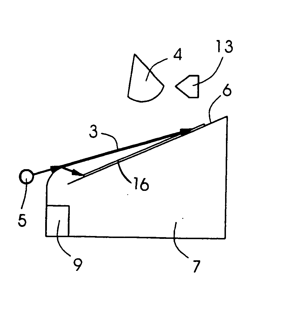
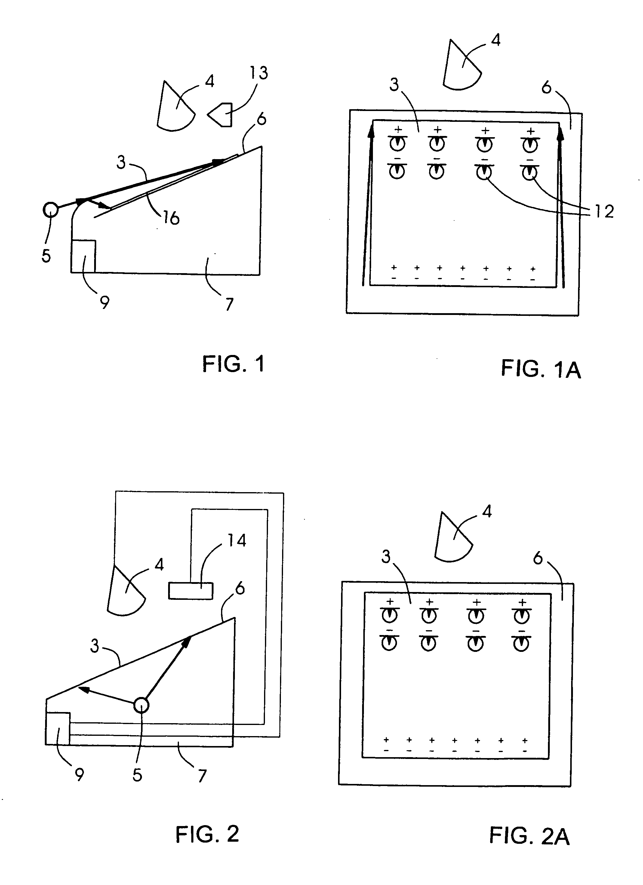
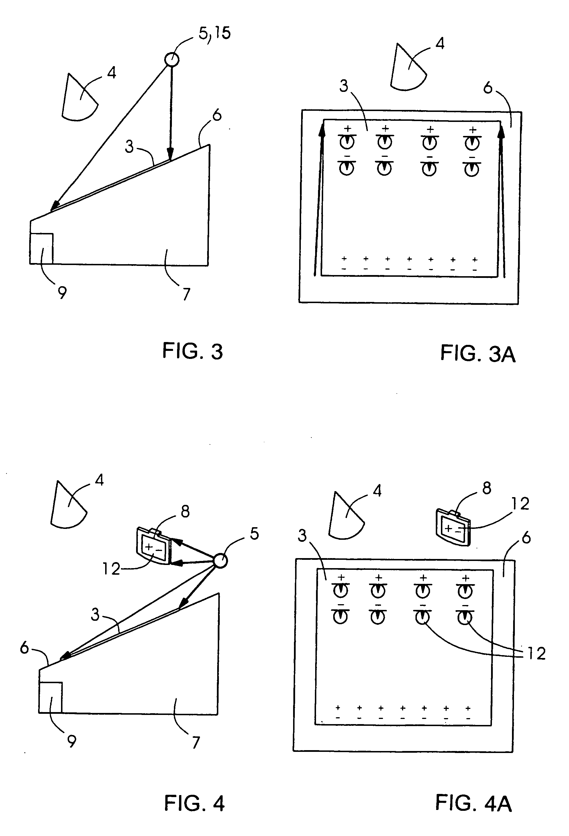
[0053] Referring now to the figures of the drawings in detail and first, particularly to FIG. 1 thereof, there is shown a sheet-supporting desk 7, which is provided with a display and operating device according to the invention, beside the control station of a press 1 (see FIG. 5). For such a purpose, the sheet-supporting desk 7 has a control computer 9 that can communicate with a video and data projector 5 and a video camera 4. The communication can, in this case, function with wires or by wireless transmission. The projector 5 is located on the front side of the sheet-supporting desk 7, at which location there is normally a printer or other operating personnel. With the projector 5, any desired image 3 can be projected onto a projection area 6 of the sheet-supporting desk 7. The projection area 6 can, in this case, be the supporting surface of the desk 7 but can also be the surface of a white or printed sheet 16. This projection area 6 is scanned by a video camera 4 fitted above t...


PUM


Abstract

A display and / or operating device for controlling machines includes a projection device for projecting an image onto a projection area, an acquisition device for scanning the same projection area, and a control computer for controlling the projection device and the acquisition device. The present invention is distinguished by the fact that, by the acquisition device and the control computer, an analysis of the same projection surface can be carried out, and that the content of the image to be projected can be controlled by the control computer as a function of the result of the analysis of the same projection area.

Description

BACKGROUND OF THE INVENTION [0001] Field of the Invention [0002] The present invention relates to a display and / or operating device for controlling machines, having a projection device for projecting an image onto a projection area, an acquisition device for scanning the projection area, and a control computer for controlling the projection device and the acquisition device. [0003] In the operation of presses, it is, nowadays, necessary for the operator to keep his eye on many operating elements and displays, which are distributed at a number of locations in the press. For example, the control desk of a press normally has a monitor, through which the most important settings on the press can be made. Furthermore, beside the monitor, there is normally a supporting desk for printed sheets, further operating elements (for example, for adjusting the inking zones of the press) being located grouped around the sheet support. In addition, there are functions on the press that can be operate...

Claims


Application Information

Patent Timeline
IPC IPC(8): B41F33/00B41F33/02B41F33/14B41F33/16G03B21/00G03B21/26G06F3/00G06F3/01G06F3/033G06F3/041G06F3/042
CPCB41F33/0036G06F3/0425G06F3/011
Inventor BERG, WINFRIEDFRANKE, VOLKHARDHAUCK, DIETERKAISER, MICHAELSCHNEIDER, MANFREDWAGENSOMMER, BERNHARD
Owner HEIDELBERGER DRUCKMASHINEN AG
Learn More