
Interior illumination lamp

Active Publication Date: 2005-08-04
YAZAKI CORP
View PDF2 Cites 5 Cited by
  • Summary
  • Abstract
  • Description
  • Claims
  • Application Information

AI Technical Summary

Benefits of technology

[0009] In view of such circumstances, it is an object of the present invention to provide an interior illumination lamp having a moving and fixing mechanism with simple structure and high durability.
[0012] Therefore, according to this interior illumination lamp, with the provision of the sliding member, which is capable of being pressed resiliently, such problem that the light source cannot be fixed to the desired direction due to abrasion or change of properties of the felt sliding member due to the temperature or deterioration with age as in the related art can be solved. Also, in comparison with the case in which the spring or the like is employed, the number of parts can be reduced, and hence increase in cost due to increase in the number of parts can be avoided.
[0014] In the interior illumination lamp configured in this manner, by causing the sliding member to be pressed against the recessed spherical surface provided inside the bezel member, the bezel member can be freely rotated, and the optical axis can be positioned in the desired direction.
[0016] In the interior illumination lamp configured as described above, since a plurality of the sliding members are provided at the radial positions on the spherical surface, the bezel member can be stably rotated and fixed. Also, with the provision of the guiding member between the sliding members, the bezel member is prevented from being rattled with respect to the main body and hence can be rotated smoothly, so as to be fixed reliably to a desired position.
[0020] In the interior illumination lamp configured in this manner, by causing the projections provided on the sliding members to be pressed against the spherical surface, the bezel member can be rotated and fixed with respect to the main body with a suitable friction.
[0021] According to the present invention, the problem in the related art such that the resiliency of the felt is reduced due to exposure to a high temperature or deterioration with age, and hence the bezel member cannot be fixed at the desired direction can be solved. Also, in comparison with the case in which a combination of a spring and a ball which are hardly affected by the temperature or deterioration with age are employed, such a problem that the number of components increase can be avoided. Accordingly, there is provided an interior illumination lamp having a moving and fixing function with a simple structure and high durability.

Problems solved by technology

Therefore, there is a problem such that when the resiliency of the felt is reduced by exposure to a high temperature or deterioration with age, the lamp body 105 cannot be fixed at the desired direction.
However, in this case, the number of parts increases, and hence the cost is increased correspondingly, and the structure becomes complex.

Method used


Image

  • Interior illumination lamp
  • Interior illumination lamp
  • Interior illumination lamp

Examples


Embodiment Construction

[0033] Referring now to the drawings, an embodiment of the present invention will be described.

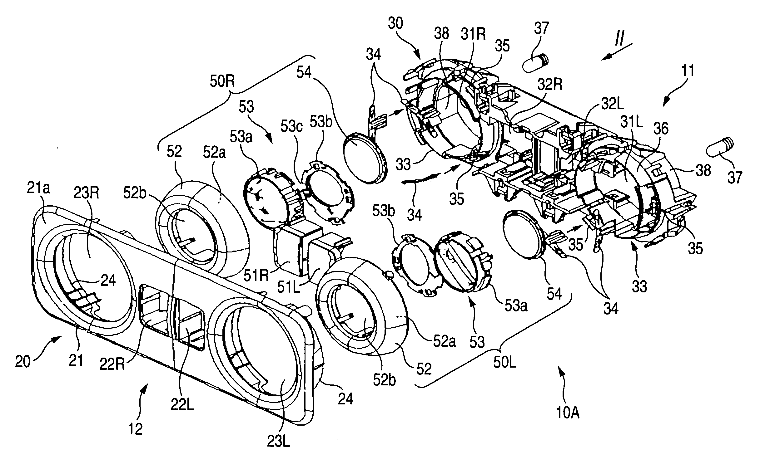
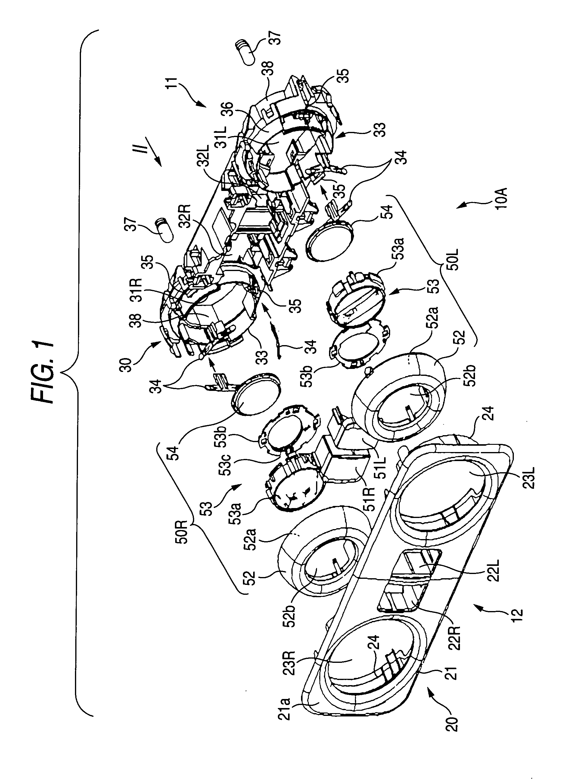
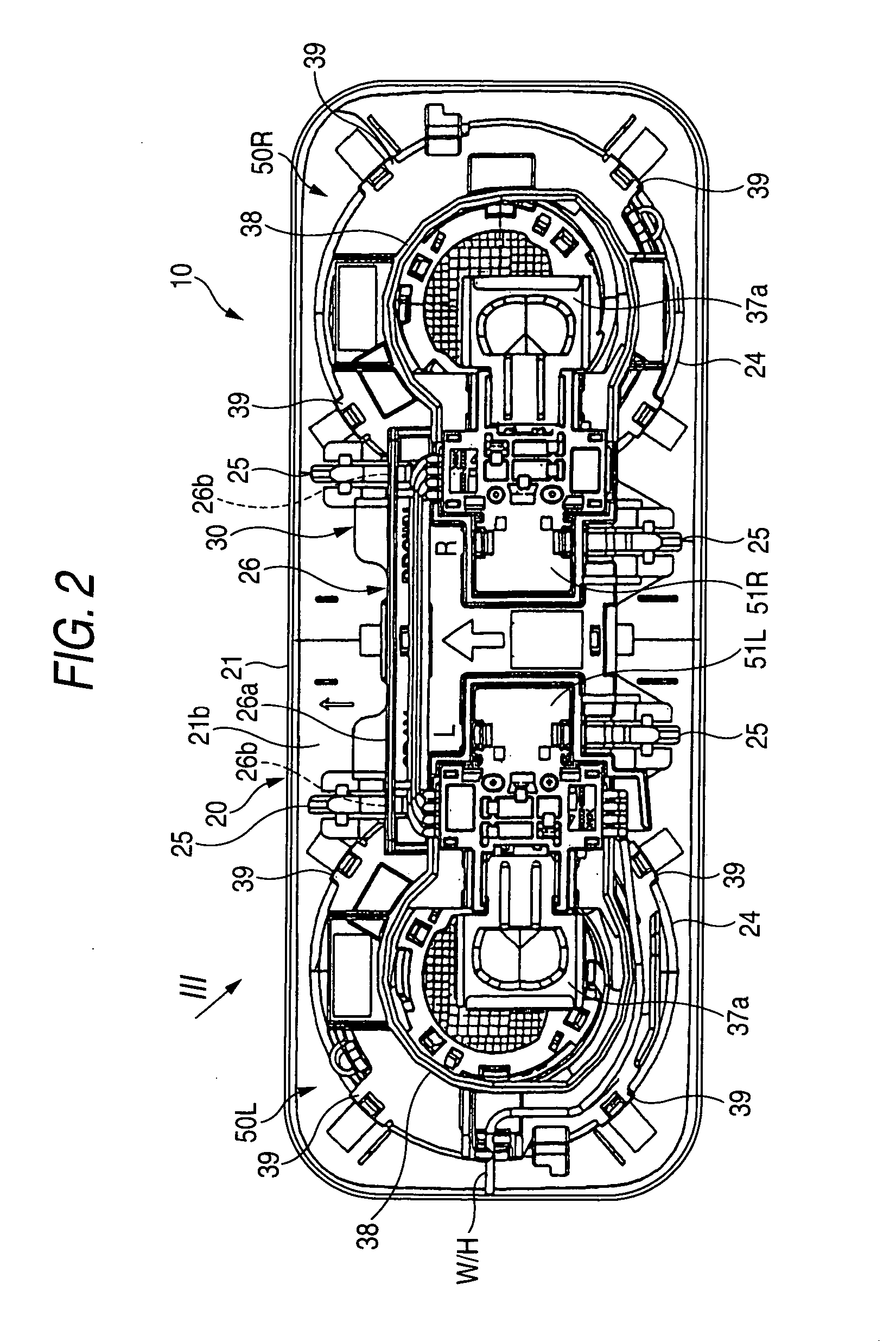
[0034] As shown in FIG. 1, an interior illumination lamp 10 according to the embodiment of the present invention includes a decorative member 20 exposed to a cabin 12 (see FIG. 7), and a functioning body 30 located inside the decorative member 20 as a main body provided with various electrical components mounted thereon.

[0035] As shown in FIG. 7, the interior illumination lamp 10 is configured such that the decorative member 20 is attached to an interior material (trim) 13 provided inside a vehicle body 11, so as to be capable of being connected easily to a wire harness W / H distributed on the back side of the interior material 13 in advance.

[0036] As sown in FIG. 1 to FIG. 3, the decorative member 20 has a surface 21a exposed to the cabin 12 and includes a frame 21 formed, for example, into a square shape. At the center of the frame 21, there are provided switch holes 22L, 22R for expos...


PUM


Abstract

A bezel member (52) to which a lens (54) which transmits light from a light source (37) is supported on a main body (30) to be fixed to a vehicle body (11). A spherical surface (52a) is formed on one of the main body (30) or a bezel member (52), and sliding members (34) for being pressed against the spherical surface (52a) are formed on the other one of them, so that the bezel member (52) can be rotated with respect to a supporting member (33) of the main body (30) and fixed to a given position. Since a metal plate is used as the sliding members (34) in this interior illumination lamp (10), a problem such that the light source cannot be fixed to the desired direction due to abrasion or change of properties of the felt sliding member as in the related art due to the temperature or deterioration with age can be solved. Also, in comparison with the case in which the spring or the like is employed, increase in cost due to increase in the number of parts can be avoided.

Description

BACKGROUND OF THE INVENTION [0001] 1. Field of the Invention [0002] The present invention relates to an interior illumination lamp and, for example, to an interior illumination lamp to be mounted to a door, a ceiling, or the like of a motor vehicle. [0003] 2. Related Art [0004] In the related art, an interior illumination lamp is shown in FIG. 10, for example, Unexamined Japanese Patent Publication 2000-1141. [0005] The interior illumination lamp is to be used by mounting to a back door of a station wagon, and is adapted to illuminate a luggage room provided at the rear or the lower part of the opened back door of the station wagon by changing the direction of illumination. [0006] As shown in FIG. 10, an interior illumination lamp 100 includes a lamp housing 102 mounted to a trim 101 defining a wall surface of the back door, and a circular opening 103 provided forwardly of the lamp housing 102. A lamp supporting member 104 having a spherical inner surface is provided rearwardly of t...

Claims


Application Information

Patent Timeline
IPC IPC(8): B60Q3/02B60Q3/06F21V21/30F21W106/00
CPCB60Q3/0253F21V21/30B60Q3/06B60Q3/30B60Q3/44
Inventor SUZUKI, HIROYUKIISHII, KIMIHIROKIMURA, MOTOYAANDO, HIROSHI
Owner YAZAKI CORP
Features
  • Generate Ideas
  • Intellectual Property
  • Life Sciences
  • Materials
  • Tech Scout
  • Unparalleled Data Quality
  • Higher Quality Content
  • 60% Fewer Hallucinations
Learn More