

Gas turbine flowpath structure
- Summary
- Abstract
- Description
- Claims
- Application Information
AI Technical Summary
Benefits of technology
Problems solved by technology
Method used
Image

Examples
Embodiment Construction
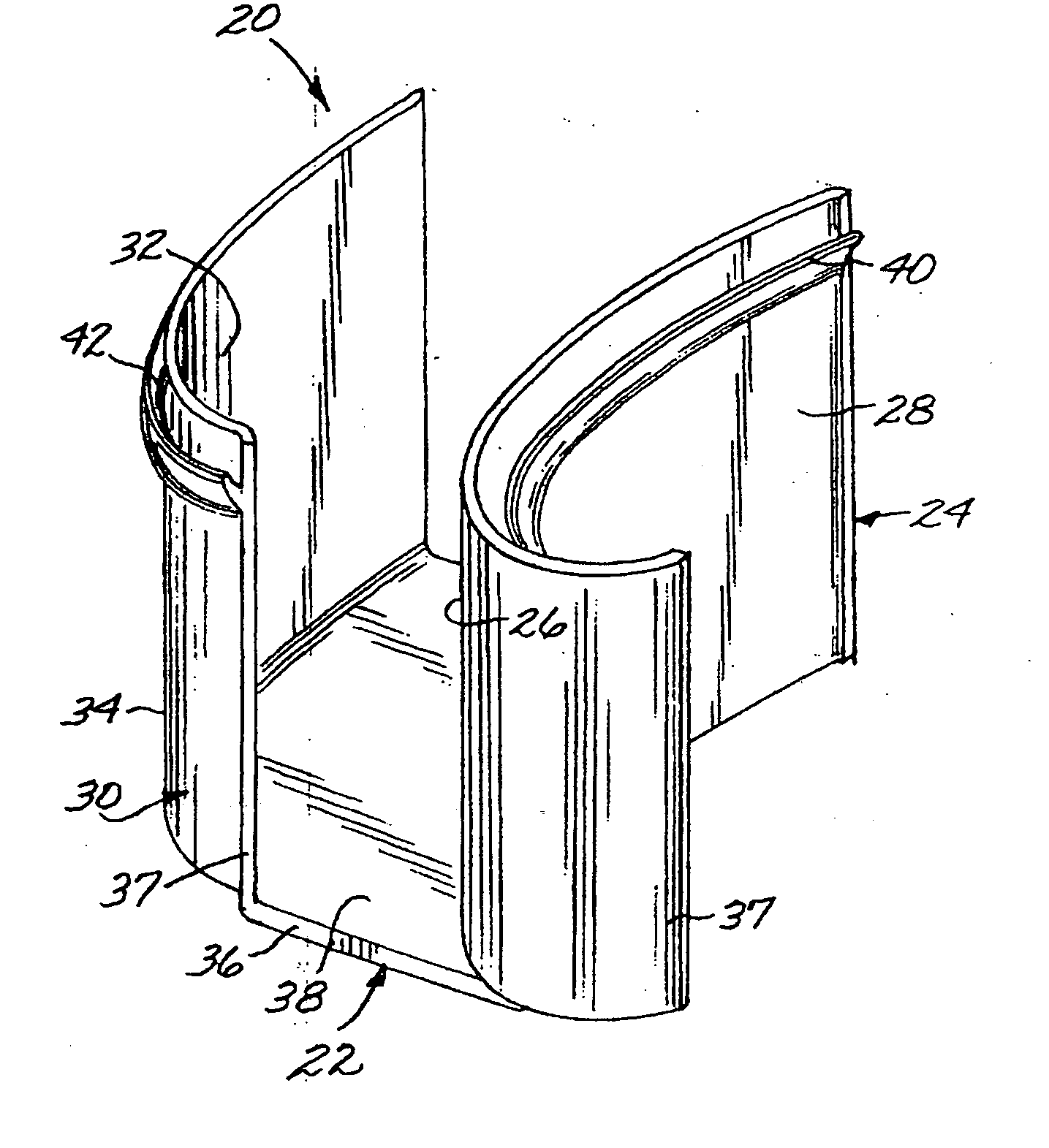
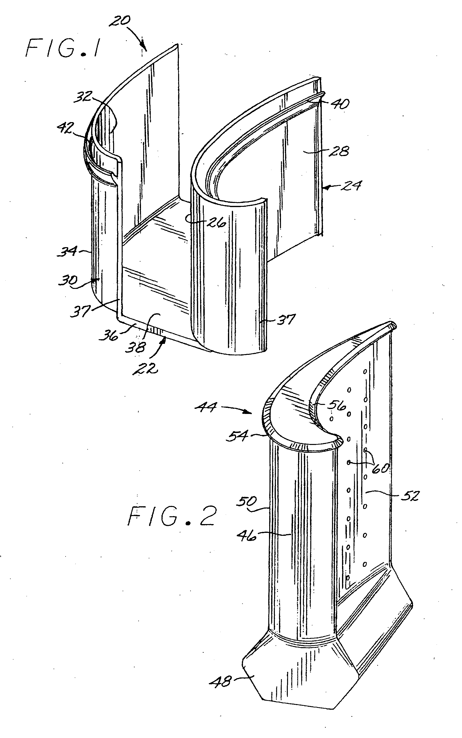
[0022]FIG. 1 depicts a portion of a turbine flowpath structure 20. The turbine flowpath structure 20 includes a first generally U-shaped flowpath channel 22 having a first leg 24 with a first inwardly facing side 26 shaped as a turbine blade suction-side airfoil surface, and a first outwardly facing side 28. The generally U-shaped flowpath channel 22 further includes a second leg 30 having a second inwardly facing side 32 shaped as a turbine blade pressure-side airfoil surface, and a second outwardly facing side 34. The turbine flowpath structure 20 further includes a web 36 connecting the first leg 24 and the second leg 30 at a location near their inboard ends 37. The web 36 has an inwardly facing inner flowpath surface 38. There is a first channel engagement shoulder 40 on the first outwardly facing side 28 of the first leg 24, and a second channel engagement shoulder 42 on the second outwardly facing side 34 of the second leg 30. The functions of these engagement shoulders 40 and...
PUM
 Abstract
Description
Claims
Application Information